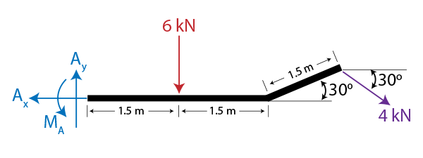
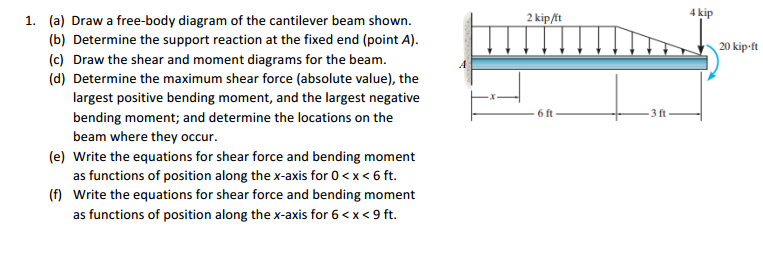
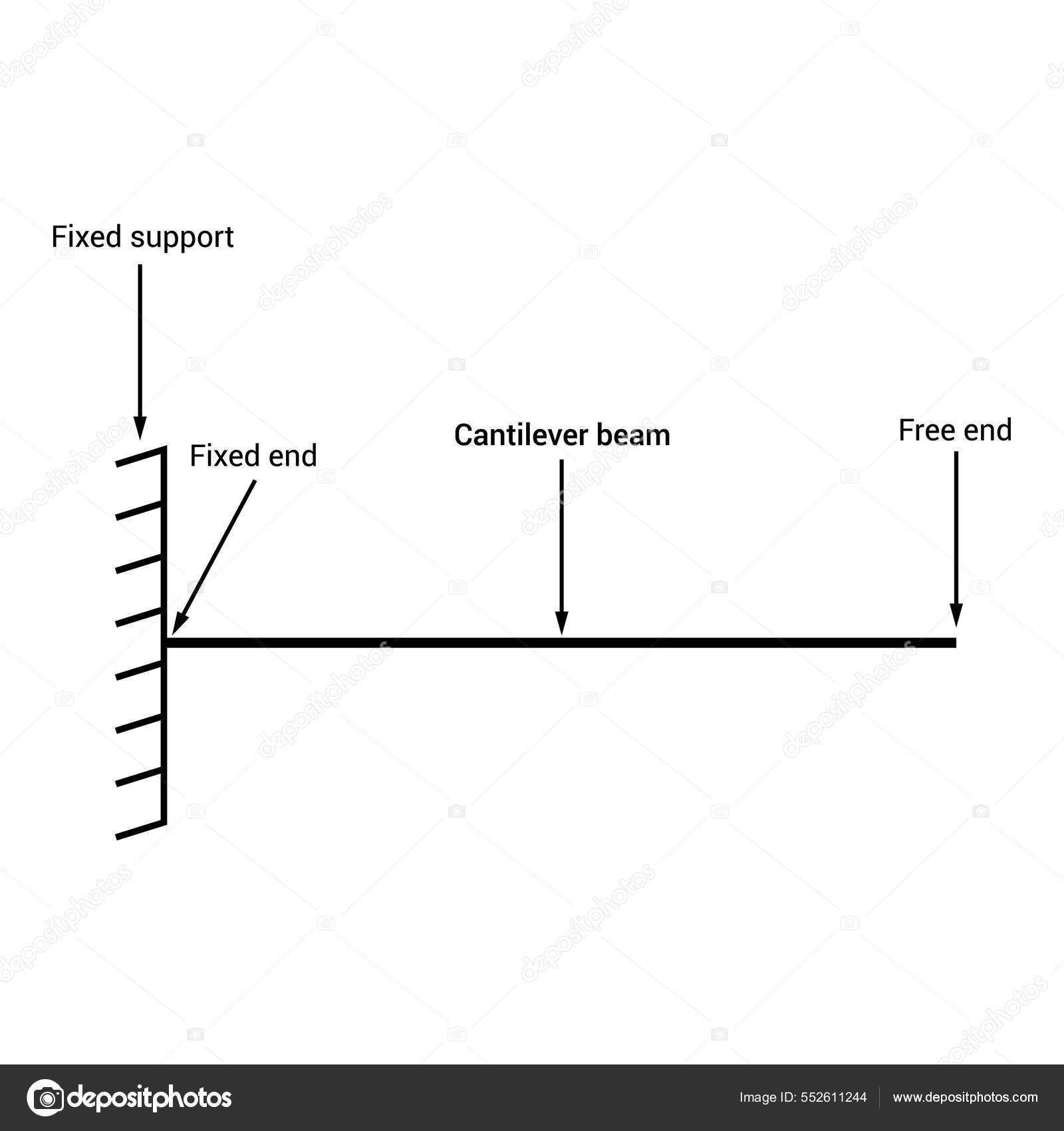
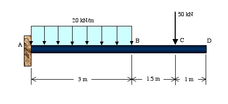
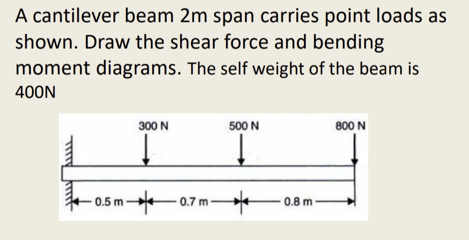
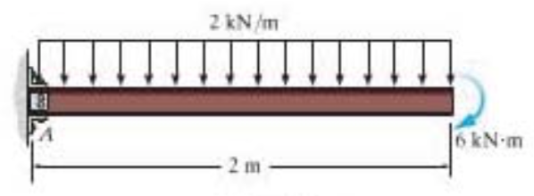
42 draw the free-body diagram for the cantilevered beam. a is the a fixed support.
draw the shear diagram for the beam 6.29 ... Shear and Moment FunctionsA free-body diagram of a beam. 4 kNm 3 m 3 m A B Prob. Draw the shear and moment diagrams for the beam shown in Fig. Reaction at the support A R A 5 3 7 2 2 6 29 t. Draw the shear and moment diagram of a beam of a 7m-simple span with an overhang of 15m weighs 3P kN per meter is loaded by 3 vertical downward forces. PDF CHAPTER 2 Shear Force And Bending Moment As a general rule, if a support prevents translation of a body in a given direction, ... Draw the free body diagram: R ... A cantilever beam is loaded as shown. Determine all reactions at support A. 5 kN/m 2 m 2 m 1 m A 20 kN 3 4 15 kNm EXAMPLE 3 .
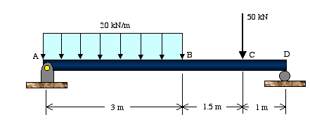
Beam Reactions and Diagrams - Strength of Materials ... Draw the beam free body diagram Replace the uniform distributed load (if any) with the equivalent point load Solve ΣM A = 0 (sum of moments about support A). This will give you R B (reaction at support B). Solve ΣM B = 0. This will give you R A. Using R A and R B found at steps 3 and 4 check if ΣV = 0 (sum of all vertical forces) is satisfied.

Draw the free-body diagram for the cantilevered beam. a is the a fixed support.
Lecture 22: Simply Supported Beams Free Body Diagram ... Lecture Description. The objectives of this video are to give an introductory overview on how to use free body diagrams to deduce support reactions followed by a comprehensive workout on support reactions example. At first, the video illustrates a given diagram of simply supported beam having a pin support at left end and a roller support at ... How to Draw a Free Body Diagram - Simply Supported Beam ... A short video to show how to form an imaginary cut and draw a free body diagram of a simply supported beam with a point load.Related videos:Reactions of a Si... Cantilever Free Body Diagram Example | Statics - YouTube for more FREE video tutorials covering Engineering Mechanics (Statics & Dynamics)The key objective of this video is to consider support...
Draw the free-body diagram for the cantilevered beam. a is the a fixed support.. Solved Part A Draw the free-body diagram for the | Chegg.com Question: Part A Draw the free-body diagram for the cantilevered beam. A is the a fixed support Draw the vectors starting at the black dots. The location and orientation of the vectors will be graded. The length of the vectors will not be graded. Double-click on the black dot to indicate the direction of the moment. What are Free Body Diagrams? - Massachusetts Institute of ... A free body diagram is a graphic, dematerialized, symbolic representation of the body (structure, element or segment of an element) in which all connecting "pieces" have been removed. A FBD is a convenient method to model the structure, structural element, or segment that is under scrutiny. (Solved) - Draw a free body diagram cantilever beam A is a ... draw a free body diagram cantilever beam A is a fixed support. Draw free body diagram for the beam A is a rocker and B is a pin 6 kN m 1.5 m 1.5 m 1 Approved Answer Satyendra K answered on January 17, 2021 5 Ratings, ( 14 Votes) solution .pdf Do you need an answer to a question different from the above? Ask your question! Next Previous Solved Draw the free-body diagram for the cantilevered ... Expert Answer Transcribed image text: Draw the free-body diagram for the cantilevered beam. A is the a fixed support. Draw the vectors starting at the black dots. The location and orientation of the vectors will be graded. The length of the vectors will not be graded. Double-click on the back dot to indicate the direction of the moment.
PDF BEAM DIAGRAMS AND FORMULAS - Arch Exam Academy beam diagrams and formulas by waterman 55 1. simple beam-uniformly distributed load ... 22. cantilever beam-concentrated load at free end. 23. beam fixed at one end, free to deflect vertically but not rotate at other-concentrated load at deflected end 24. beam overhanging one support-uniformly distributed load. 25. beam overhanging one support ... virtual-mode.de Determine the magnitude of the pin reaction at a Animals. Arts and Literature Cantilever Beam - Uniformly Distributed Load Cantilever Beam - Uniformly Distributed LoadMore Beams. Max. Moment, M max: The above beam deflection and resultant force calculator is based on the provided equations and does not account for all mathematical and beam theory limitations. The calculator has been provided with educational purposes in mind and should be used accordingly. PDF Unit M4 - Massachusetts Institute of Technology 1. Draw Free Body Diagram 2. Apply Equilibrium Example: Cantilevered Flag Figure M4.3-8 Geometry and free body diagram of cantilevered flag z x ~ ~ ~ • x z m = mass/unit length mg H A V A M A f f L L FREE BODY DIAGRAM:
Draw Bending Moment & Shear Force Diagrams - Cantilever Beam This video explains how to draw shear force diagram and bending moment diagram with easy steps for a cantilever beam loaded with a concentrated load. Shear f... Free Online Beam Calculator for Cantilever or ... - SkyCiv Free online beam calculator for generating the reactions, calculating the deflection of a steel or wood beam, drawing the shear and moment diagrams for the beam. This is the free version of our full SkyCiv Beam Software. This can be accessed under any of our Paid Accounts, which also includes a full structural analysis software. Part A Draw the free-body diagram for the cantilevered beam. Part A Draw the free-body diagram for the cantilevered beam. A is the a fixed support. Draw the vectors starting at the black dots. The location and orientation of the vectors will be graded. The length of the vectors will not be graded. Double-click on the black dot to indicate the direction of the moment. (PDF) Shigley's Mechanical Engineering Design 8th Edition ... Enter the email address you signed up with and we'll email you a reset link.
Example 6 - Aerospace Engineering Reaction loads: As shown in the free-body diagram, there are three unknown reactions that need to be solved for using the equilibrium condition. Since this represents a two-dimensional force system, we can only make use of three equilibrium equations. We begin the solution by using the equilibrium of moments with point A as the moment center.
Answered: a) Draw a free body diagram of the… | bartleby 4. Transcribed Image Text: a) Draw a free body diagram of the beam. b) Determine the reactions at the support at point A. 200 h 300 Ib 6ft.
5.2: Free Body Diagrams - Engineering LibreTexts Aug 30, 2021 · Drawing a correct free-body diagram is the first and most important step in the process of solving an equilibrium problem. It is the basis for all the equilibrium equations you will write; if your free-body diagram is incorrect then your equations, analysis, and solutions will be wrong as well.
Draw the free-body diagram for the following problems. a ... Engineering Mechanical Engineering INTERNATIONAL EDITION---Engineering Mechanics: Statics, 14th edition (SI unit) Draw the free-body diagram for the following problems. a. The cantilevered beam in Prob. 5-10. b. The beam in Prob. 5-11. c. The beam in Prob. 5-12. d. The beam in Prob. 5-14.
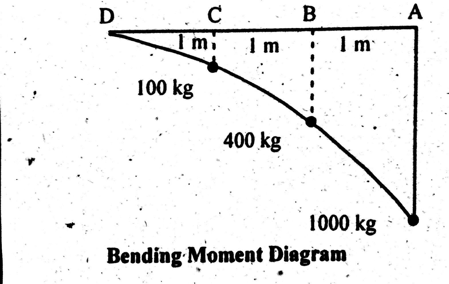
Bending moment and shear force diagram of a cantilever beam In this article Learn :cantilever beam Bending moment diagram B.M.D. and shear force diagram S.F.D. of a cantilever beam having point load at the end,several point loads,U.D.L. Over Whole Span ,U.D.L. not over the whole span,U.D.L. from support to some distance,U.D.L. Somewhere on the beam,Combination of Point Loads and U.D.L.
(Get Answer) - Vectors: F A , B x, B y Part A Draw the ... Vectors: F A , B x, B y Part A Draw the free-body diagram for the cantilevered beam. A is the a fixed support. Draw the vectors starting at the black dots. The location and orientation of the vectors will be graded. The length of the vectors will not be graded. Double-click on the black dot to indicate the direction of the moment.
Determine the components of the support ... - YouTube Book: videos: my official student: the compo...
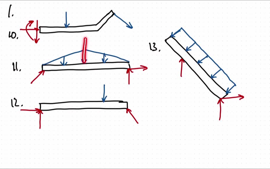
draw the free body diagram for the following problems a the cantilevered beam in prob 5 10 b the b 2
Answered: Draw free body diagram of the beam… | bartleby Draw free body diagram of the beam shown in Figure. 2.17 You can use Microsoft excel in making the V and M diagram. W = 3kN/m A D B 2.0m C 2.0m 2.0m Figure 2.17. Question. ... A cantilever beam with the fixed support on the left is under the loadings below, w = 6n Note: ...
Solved Part A Draw the free-body diagram for the | Chegg.com Part A Draw the free-body diagram for the cantilevered beam. A is the a fixed support. Draw the vectors starting at the black dots. The location and orientation of the vectors will be graded. The length of the vectors will not be graded. Double-click on the black direction of the moment. To change the direction click on the dot one more time.
Ch06 07 pure bending & transverse shear - SlideShare 19.05.2018 · Draw the shear and moment diagrams for the cantilevered beam. 300 lb 200 lb/ft A 6 ft The free-body diagram of the beam’s left segment sectioned through an arbitrary point shown in Fig. b will be used to write the shear and moment equations. The intensity of the triangular distributed load at the point of sectioning is Referring to Fig. b, w = 200a x 6 b = …
draw the free-body diagram for the cantilevered beam ... Mar 31, 2022 · Part A Draw the free-body diagram for the cantilevered beam. A is the a fixed support Draw the vectors starting at the black dots. The location and orientation of the vectors will be graded. Use this steel i beam span calculator to determine the reactions at the supports draw the shear and moment diagram for the beam and calculate the.
(PDF) Mechanics of materials solution manual - Academia.edu mechanics of materials solution manual. Chapter# 6-14. Enter the email address you signed up with and we'll email you a reset link.
Statics: Free Body Diagrams - Engineering Statics The basic process for drawing a free body diagrams is Select and isolate an object. The "free-body" in free-body diagram means that the body to be analyzed must be free from the supports that are physically holding it in place Simply sketch a quick outline of the object as if it is floating in space disconnected from everything.
Cantilever Free Body Diagram Example | Statics - YouTube for more FREE video tutorials covering Engineering Mechanics (Statics & Dynamics)The key objective of this video is to consider support...
How to Draw a Free Body Diagram - Simply Supported Beam ... A short video to show how to form an imaginary cut and draw a free body diagram of a simply supported beam with a point load.Related videos:Reactions of a Si...
Lecture 22: Simply Supported Beams Free Body Diagram ... Lecture Description. The objectives of this video are to give an introductory overview on how to use free body diagrams to deduce support reactions followed by a comprehensive workout on support reactions example. At first, the video illustrates a given diagram of simply supported beam having a pin support at left end and a roller support at ...















0 Response to "42 draw the free-body diagram for the cantilevered beam. a is the a fixed support."
Post a Comment