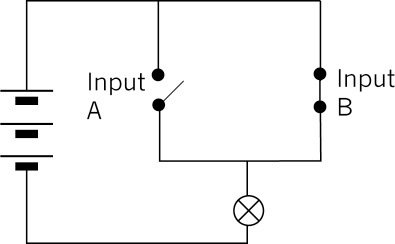
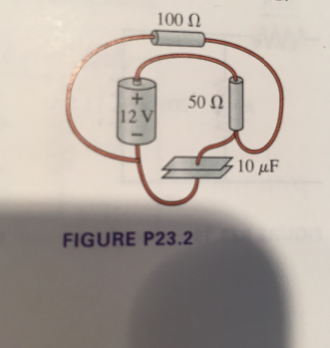
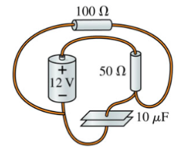
42 draw a circuit diagram for the circuit of (figure 1) .
Experiment with an electronics kit! Build circuits with batteries, resistors, ideal and non-Ohmic light bulbs, fuses, and switches. Determine if everyday objects are conductors or insulators, and take measurements with an ammeter and voltmeter. View the circuit as a schematic diagram, or switch to a lifelike view. Transcribed image text: Draw a circuit diagram for the circuit of (Figure 1). Choose the correct diagram. 10μF 12 V 50 Ω 100 50 0 10μF 12 V 100 ww 50 12 V Figure 1 of 1 100 Ω 10μF 100 100 + 50 12 V 12 V 50 10 μF 10μF WW wwW + +
Description : Explain working of AC circuit breaker using SCR with circuit diagram. Last Answer : AC Circuit Breaker: The circuit configuration of static AC circuit breaker using SCR is shown in the figure. When switch S' is closed, the SCRs T1 and T2 are fired in positive ... to non-availability of gate current. Thus the maximum time delay for breaking the circuit is one half-cycle.

Draw a circuit diagram for the circuit of (figure 1) .
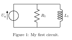
Fig. 1. Sample circuit diagrams from both the no labels (N) conditions ... drawing diagrams and making annotations in order to determine how the code can ... Figure 1 shows a circuit diagram of a very simple three-resistor series-parallel circuit. Resistors R 2 and R 3 are seen to be connected in parallel, and resistor R 1 … Draw the circuit shown in Figure 5.1 using PSpice. The DC current sources in this circuit are independent current sources. Independent current sources can be placed by typing IDC in the place part field. 2. Find the values of the node voltages V a, V b, V c and V d.
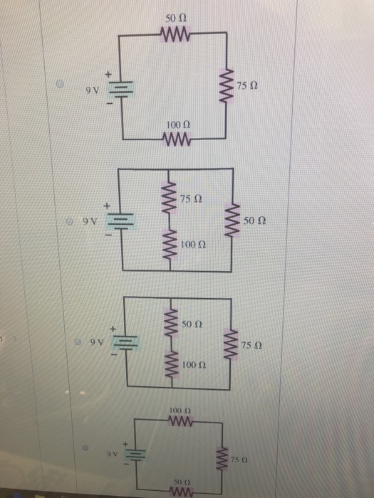
Draw a circuit diagram for the circuit of (figure 1) .. A circuit drawing allows you to visualize how components of a circuit are laid out. Lines connect fuses, switches, capacitors, inductors, and more. SmartDraw comes with thousands of detailed electrical symbols you can drag and drop to your drawings and schematics. SmartDraw also comes with a number of built-in circuit and wiring diagram ... Draw a circuit diagram for the circuit of (Figure 1). Figure 1 of 1A circuit is shown in the figure. A 9-volt battery is connected by wires to different resistors. The positive terminal of the battery is connected to a 50-ohm resistor by one wire and to a 75-ohm resistor by another wire. A 50-ohm resistor is connected directly to the 100-ohm ... Dec 20, 2017 · Circuit Diagram: The complete circuit diagram for this Fire Fighting Robot is given below. You can either connect all the shown connections for uploading the program to check the working or you can assemble the bot completely and then proceed with the connections. Both ways the connections are very simple and you should be able to get it right. 1. Use a block diagram to draw the circuit of a single - celled light bulb and switch that are placed together. 15 INDEPENDENT ACTIVITY 3 Draw on a separate sheet of paper the diagram of a lamp shade with a switch powered by a 9v battery. INDEPENDENT ASSESSMENT 3 Match the symbol to the electrical component it represents.
Feb 25, 2020 · The next transformerless 0-300V variable power supply circuit diagram can be understood with the following points:As can be seen in the figure, a high voltage transistor BF458 is used as the main load handling device. ... You cannot draw more than 1.3 amps (max) from this series battery set up for your saw machine. ... The circuit diagram to represent the circuit shown in figure can be drawn as mentioned above in the fig. Answer verified by Toppr. 174 Views. Jul 20, 2021 · Best for who is finding circuits: 0-12V and 0-24V variable power supply circuit diagram. Because It is high current, normal parts, a new circuit design.. Why should make 0-30V variable Power Supply. Modern design—I used to show you the old circuit below, also using LM723.But it … We've seen the Symbols of the Most Common Electrical Components that are used to represent them. In this video, we will look at how to draw Circuit Diagrams ...
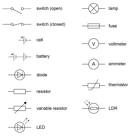
Components of Circuit Diagram. In this section, let us learn about some important circuit diagram symbols. An electric cell: It provides the source of current. In its symbol, the larger terminal is positive, whereas the smaller one is the negative terminal. A battery: It is a combination of cells and its utility is the same as the cell. Micah Watson 4/26/2020 Principles to Physics II HW 08 CH 28 Fundamentals of Circuits from page 790 [2] Draw a circuit diagram for the circuit of FIGURE EX28.2. FIGURE EX28.2 [3] In FIGURE EX 28.3, what is the magnitude of the current in the wire to the Solved: Draw A Circuit Diagram For The Circuit Of (Figure ... | Chegg.com. science. physics. physics questions and answers. Draw A Circuit Diagram For The Circuit Of (Figure 1) . Choose The Correct Diagram: Question: Draw A Circuit Diagram For The Circuit Of (Figure 1) . Choose The Correct Diagram: In some cases, a resistor-capacitor coupled filter (RC) is also used. The circuit diagram below shows a half wave rectifier with capacitor filter. Half Wave Rectifier with Capacitor Filter - Circuit Diagram & Output Waveform Half Wave Rectifier Analysis. The following parameters will be explained for the analysis of Half Wave Rectifier:-1.
Series Rlc Circuit Circuit Phasor Diagram Electrical4u
The terminal voltage V 2 across the load is equal to the induced emf E 2 in the secondary winding less voltage drop in the secondary winding.. Equivalent Circuit when all the quantities are referred to Primary side. In this case, to draw the equivalent circuit of the transformer all the quantities are to be referred to the primary as shown in the figure below:
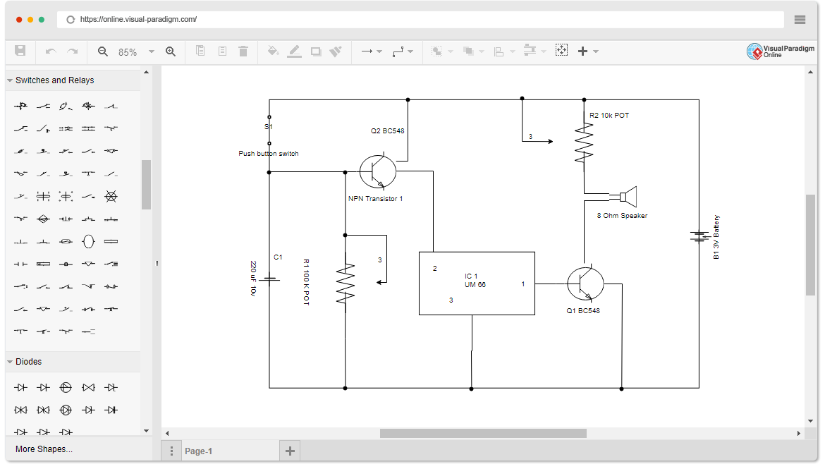
Circuit Diagram Software
The phasor diagram of the RC series circuit is shown below: Steps to draw a Phasor Diagram. The following steps are used to draw the phasor diagram of RC Series circuit. Take the current I (r.m.s value) as a reference vector; Voltage drop in resistance VR = IR is taken in phase with the current vector; Voltage drop in capacitive reactance VC ...
Solved Chapter 18 Problem 21 Introductory Circuit Analysis 13th Edition
Sep 03, 2020 · The first PIR circuit diagram for sensing moving humans is shown above. A practical implementation of the explained pin-out details can be witnessed here. In the presence of a human IR radiation, the sensor detects the radiations and instantly converts it into minute electrical pulses, enough to trigger the transistor into conduction, making ...

Series Parallel Dc Circuits Worksheet Dc Electric Circuits
Circuit Analysis -O +15V RI 42KQ R2 75k 8 4 4 7 7 -O Vo1 3 3 555 555 R3 2 2 30k 5 1 6 CI C3 C4 0.01uF C2 0.01 uF 47NF 33nF FIGURE 04(b) st shown in Figure Q4(b) Two 555 timers are connected together as Draw and completely label the waveforms for Vo,...
Gr9 Technology
Experts are tested by Chegg as specialists in their subject area. We review their content and use your feedback to keep the quality high. Transcribed image text: Draw a circuit diagram for the circuit of (Figure 1).
Solved Draw A Circuit Diagram For The Circuit Of Figure 1 Chegg Com
Draw the circuit diagram to represent the circuit shown in Fig.14.21. electric current and its effects; class-7; Share It On Facebook Twitter Email. 1 Answer +1 vote . answered Jan 20, 2018 by sameer (54.5k points) selected Jan 26, 2018 by sarthaks . Best answer. Answer is ----- ...
1
To draw a circuit diagram from a complex circuit follow the steps as: 1.Start with a collection of electrical symbols appropriate for diagram. 2.Draw circuits represented by lines from the complex given circuit. 3.Drag and drop symbols to the circuits as per the components given in the circuit and connect them appropriately.
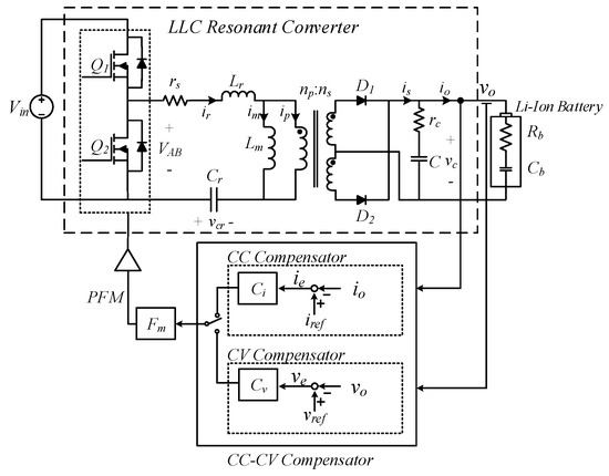
Energies Free Full Text An Integrated Current Voltage Compensator Design Method For Stable Constant Voltage And Current Source Operation Of Llc Resonant Converters
Figure 2—Circuit drawing Line diagram: a one-line diagram or single-line diagram is a simplified notation for representing an electrical system. The one-line diagram is similar to a block diagram except that electrical elements such as switches, circuit breakers, transformers, and capacitors are shown by standardized schematic symbols.

Draw The Circuit Diagram To Represent The Circuit Shown In F Scholr
Also, a SPICE tool is very handy for drawing and simulating analog circuits, but won't do much for you if you want to draw up a diagram for a mixed-signal or digital circuit. Figure 3. The LTspice circuit simulation tool. Schematics for Building. If you need to build a circuit, either breadboard or PCB (printed circuit board), then you'll ...

Neural Circuit Diagrams Nature Methods
4 answersHi. It is clear from the given figure that the two resistance is off 50 own and 100 home, uh, in Siris. Then this city's combination is in parallel with 75 ...
Circuit Diagram Simple Circuits Electricity And Circuits Don T Memorise Youtube
Electric circuits can be described in a variety of ways. An electric circuit is commonly described with mere words like A light bulb is connected to a D-cell . Another means of describing a circuit is to simply draw it. A final means of describing an electric circuit is by use of conventional circuit symbols to provide a schematic diagram of the circuit and its components.

Series Rlc Circuit And Rlc Series Circuit Analysis
Nov 10, 2020 — IL Draw the Pictorial Diagram of the given circuit (Figure 1) and show how the Ammeters and Voltmeters will be connected to measure the ...
Draw A Circuit Diagram Of An Electric Circuit Containing A Cell Myaptitude In
Draw A Circuit Diagram For The Circuit Of Figure 1 Figure 1 Of 1a Circuit Is Shown In The Figure A 9 Volt Batter Homeworklib F in d step-by-step Physics solutions and your answer to the follow in g textbook question: Consider the portion of a circuit in Figure 17.73.
Circuit
x 1 x 2 x n x 1 x 2 … x n + + + x 1 x 2 x 1 x 2 + x 1 x 2 x n x 1 x 2 x 1 x 2 ⋅ 2 … n (a) AND gates (b) OR gates x x Figure 2.8. The basic gates.

Digital Mosfet Circuits Electronics Tutorials
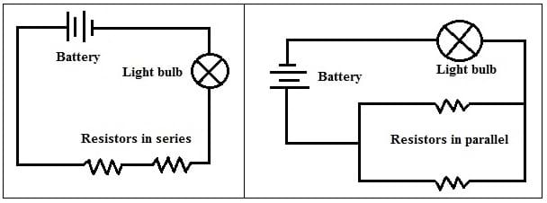
Draw a circuit with resistors in parallel and in series. Calculate the voltage ... In part a of the figure, resistors labeled R sub 1, R sub 2. Figure 1.

Control Circuit Diagram For The Sc In Figure 1 If The Single Phase Pq Download Scientific Diagram
Nov 01, 2017 · 6. Draw the Reactance Diagram The completed reactance diagram is shown in Figure 5: TXLs should be j0.13724 (my correction) Figure 5 – Single line reactance circuit diagram (reactances shown on a per-unit basis) 7. Calculate Operating Conditions of the Motors If the motors are operating at 12 kV, this represents 12 kV/13.8 kV = 0.87 per-unit ...
Circuit Diagrams In Latex Using Circuitikz Latex Tutorial Com
Solution: In the given circuit, one end of the bulb is connected with one end of the cell while their other terminals are connected to a safety pin. However, the safety pin is not connected with one of the drawing pins. Thus, the circuit is not complete. Hence, the safety pin represents a switch in the 'OFF' position. Set your child up for ...
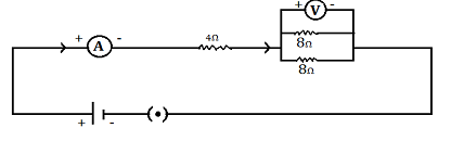
Carefully Study The Circuit Diagram In Figure And Calculate The Value Of Resistor X Sarthaks Econnect Largest Online Education Community
Draw a circuit diagram from a simple expression. Think about how you would draw a logic gate diagram for the Boolean expression: Q, equals, A, and, B, or, C, Q = A ∧ B ∨ C. You might draw the diagram in one of the two following ways: Figure 1: Option A. Figure 2: Option B. The correct diagram is option A.
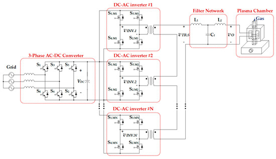
Energies Free Full Text Control Strategy For Power Conversion Systems In Plasma Generators With High Power Quality And Efficiency Considering Entire Load Conditions
Explanation. Step 1. 1 of 2. The circuit diagram of the basic inverting amplifier configuration is shown in figure below. Expression for the closed-loop voltage gain. A v A_v A v . if the circuit is: A v = v o v i n A_v=\frac {v_o} {v_ {in}} A v = v in v o . Input voltage.
Circuits One Path For Electricity Lesson Teachengineering
Generating Schematic Diagrams from Boolean Expressions. Now, we must generate a schematic diagram from this Boolean expression. To do this, evaluate the expression, following proper mathematical order of operations (multiplication before addition, operations inside parentheses before anything else), and draw gates for each step.

Electric Circuits It S All About Nodes Branches And Loops
1-408-294-8324 thetech.org This activity is meant to extend your students' knowledge of the topics covered in our Simplicity of Electricity lab. In this activity, students will learn how to draw circuit diagrams and figure out if their circuit diagram will produce a working circuit. Grade Levels: 4-8 Estimated Time: 45 minutes Student ...

Circuit Diagram Figure 1 Shows The Block Diagram Of Project Here Download Scientific Diagram
Problem Details. Draw the circuit diagram for the circuit of (Figure 1). Choose the correct options. All Physics Practice Problems !! Resistor-Capacitor Circuits Practice Problems. See all problems in !! Resistor-Capacitor Circuits.
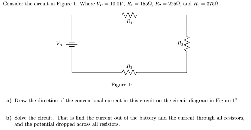
Solved Consider The Circuit In Figure 1 Where Vb 10 0v Ri 15502 R2 22502 And Rx 37502 Figure 1 Draw The Direction Of The Conventional Current In This Circuit On The Circuit
Draw a circuit diagram for the circuit of FIGURE EX28.1. View Answer. (a) Draw a circuit diagram for an LFSR with n = 6 that generates a maximum-length sequence. (b) Add logic so that 000000 is included in the sequence. (c) Determine the 10 elements of the sequence starting in... View Answer.
How To Create Circuit Diagram
Slide Topic: Sample Circuit Diagrams From Both The No Labels N Conditions Only Download Scientific Diagram Draw A Circuit Diagram For The Circuit Of Figure 1: Presentation Time: 24+ minutes: File Format: PPTX: File size: 1.5mb: Number of Pages: 55+ slides: Publication Date: December 2017

Draw A Circuit Diagram For The Circuit Of Figure 1 You May Want To Review Page Homeworklib
Draw the circuit shown in Figure 5.1 using PSpice. The DC current sources in this circuit are independent current sources. Independent current sources can be placed by typing IDC in the place part field. 2. Find the values of the node voltages V a, V b, V c and V d.

A Novel Multi Output High Voltage Isolated Power Supply System For Semiconductor Device Series Connected Switches Hou 2017 Ieej Transactions On Electrical And Electronic Engineering Wiley Online Library
Figure 1 shows a circuit diagram of a very simple three-resistor series-parallel circuit. Resistors R 2 and R 3 are seen to be connected in parallel, and resistor R 1 …

Transferring From Schematic To Wiring Diagram For Connection Purposes Basic Motor Control
Fig. 1. Sample circuit diagrams from both the no labels (N) conditions ... drawing diagrams and making annotations in order to determine how the code can ...
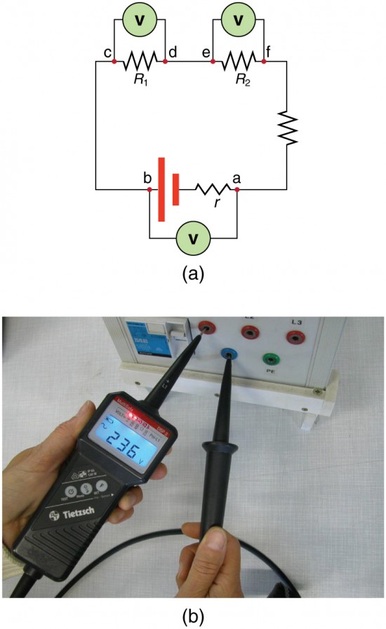
Dc Voltmeters And Ammeters Physics
Solved Draw A Circuit Diagram For The Circuit Of Figure Chegg Com

How To Draw Circuit Diagrams In Word By Saint Asky Medium

Solved Draw A Circuit Diagram For The Circuit Of Figure Chegg Com

48v Backplane Impedance Analyzer Takes The Guesswork Out Of Sizing Clippers And Snubbers Analog Devices
Draw The Circuit Diagram For The Circuit O Clutch Prep
What Is The Difference Between Circuit Diagram And Schematic Diagram Quora

Circuit Diagram For Temperature Measurement And Control System Download Scientific Diagram

Circuit Diagram Of The Wheatstone Bridge Fluxgate Sensor 1 Saturation Download Scientific Diagram
Solved Determine The Current I For Each Of The Congurations Of Fig 155 Using The Approximate Equivalent Model For The Diode B Fig 155 Problem 5 Course Hero
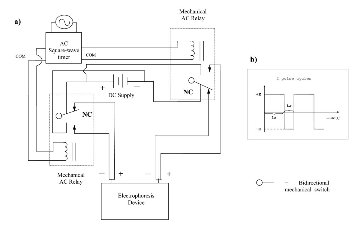
Figure 1 Increase In Local Protein Concentration By Field Inversion Gel Electrophoresis Springerlink

Solved Draw A Circuit Diagram For The Circuit Of Figure 1 Chegg Com
Circuit Diagrams Gcse Physics Combined Science Aqa Revision Study Rocket
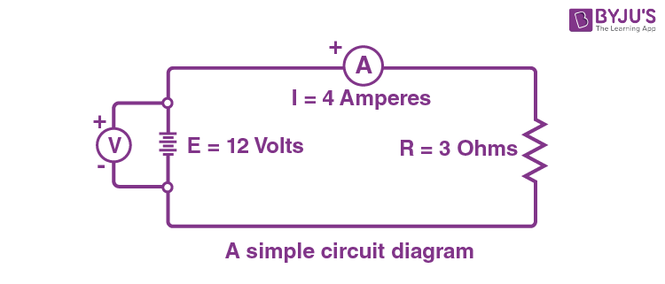
Circuit Diagram And Its Components Explanation With Circuit Symbols

Circuit Diagram For Tcd Download Scientific Diagram
0 Response to "42 draw a circuit diagram for the circuit of (figure 1) ."
Post a Comment