42 delay on break timer wiring diagram
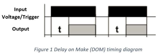
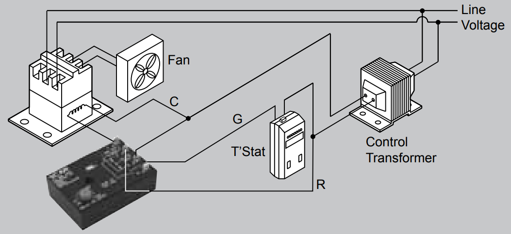
PDF Users Guide Mc-25 Delay on Make, Delay on Break Time Delay The MC-25 (PN: 10MC25) is a delay on make, delay on break time delay. It is perfect to use when either a magnetic lock or electric strike is installed on an automatic door. The delay on break timer will release the lock and then the delay on make timer will enable the door to open and be held open for a set period of time. HVAC Delay On Make Timer (How it works & How To Wire ... Today we will go over what is a HVAC delay on make timer and how it works, how to wire the delay on make timer and when to use a delay on make time delay for...
ICS Time Delay Module Applications and Wiring Figure 1. The KH1 Series adjustable ON DELAY module connection diagram. View is from the flat side with the catalog numbers. Time delay is variable and dependent on the resistance value of Rt. Rt @ 0 Ohm = minimum delay, Rt @ 1M Ohm = maximum delay. Module LOAD at Pin 2 is a relay coil.

Delay on break timer wiring diagram
The Basics of Time Delay Relays. Aug. 1, 2010. Application requirements for time delay relays (TDRs) David Bredhold. No matter what the application is, when a definite-purpose solution is required, time delay relays (TDRs) can provide simple, reliable, and economical control. Adjusting the delay time is often as simple as turning a knob. Delay on Break Timer Time Delay Relays - Littelfuse Delay on break timers from Littelfuse provide reliable and lasting protection for direct operation of heavy loads. ... Wiring Accessories; Polymer ESD Suppressors. ... Time Delay Range: 0.5 - 60 s externally adjustable, 0.5 - 60 s onboard adjustable, ... Interface GSM Module to Arduino - Send and Receive SMS In this article, we are going to see how to interface the GSM Module with Arduino.There are different kinds of GSM modules available on the market. We are using the most popular module based on Simcom SIM900 and Arduino Uno for this tutorial.
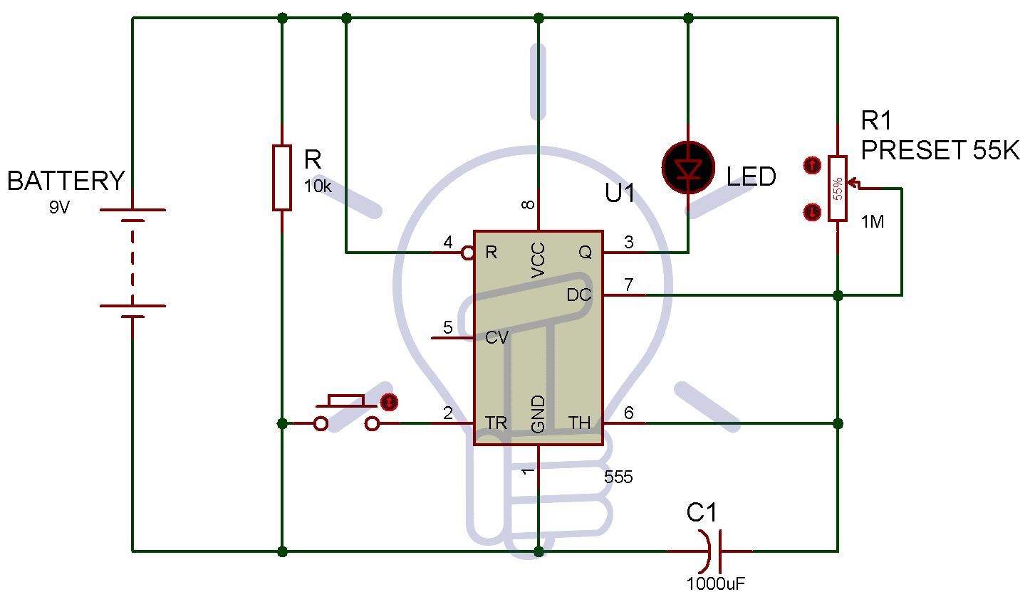
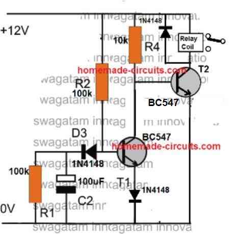
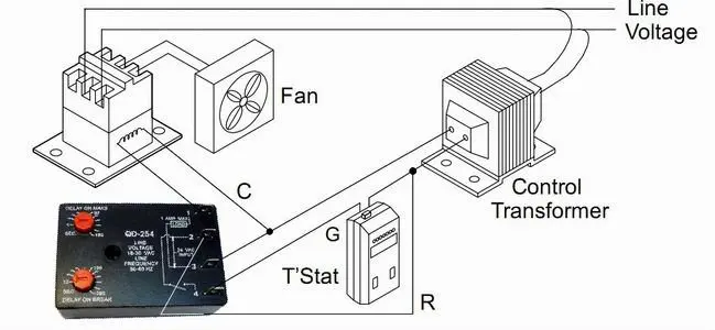
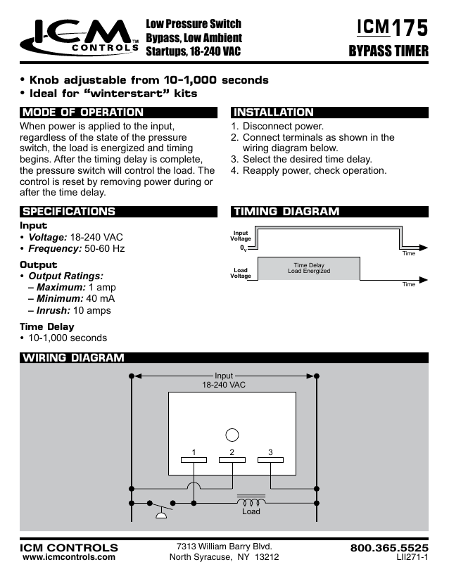
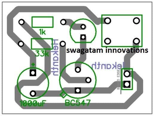
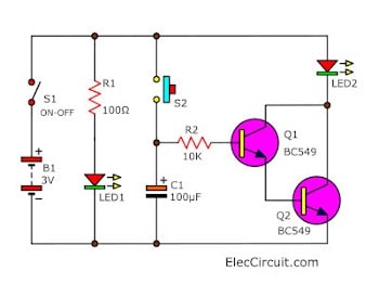
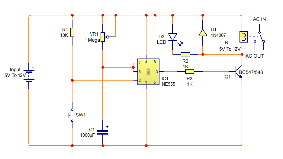
Delay on break timer wiring diagram. House Defense | Terraria Wiki | Fandom To create this all you need is wiring, a trigger (p. plate, lever, etc.), a door, and a timer (the faster the better). Place your door down wherever and place wire directly in front and in back of the door, hook the wiring up to your trigger (switches are usually better for this) and place the timer somewhere in the wiring. Activating the trigger will now make sure if the door gets opened it ... PDF ON Delay/OFF Delay ICM254 - ICM CONTROLS Time Delays (Adjustable Only) • ON delay: 1-180 seconds • OFF delay: 12-390 seconds INSTALLATION 1.Disconnect power. 2. Connect terminals as shown in the wiring diagram below. 3. Select desired delay on make and delay on break periods. 4. Reapply power, check operation. MODE OF OPERATION Power must be applied at all times. Adjustable Timer Circuit Diagram with Relay Output To prevent 555 timer from flyback current in the relay use a diode before the relay. Some 555 versions may get damaged because of this. [Also Read: 12V Time Delay Relay] Adjustable ON OFF Timer(using 555 astable mode) In this circuit a timer with cyclic on off operations is designed. Simple Delay Timer Circuits Explained - Homemade Circuit ... Simple Delay Timer Circuits Explained. In this post we discuss the making of simple delay timers using very ordinary components like transistors, capacitors and diodes. All these circuits will produce delay ON or delay OFF time intervals at the output for a predetermined period, from a few seconds to many minutes.
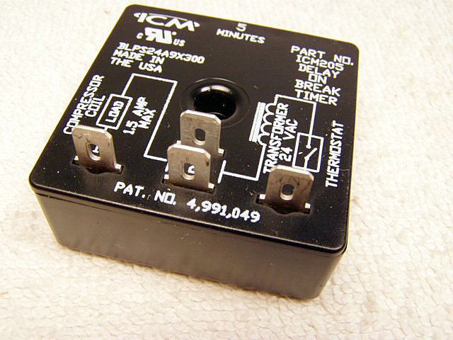
Time Delay on break for compressor - YouTube The time delay on break, how it works, how to wire into low voltage,and why you should have it on your compressor. Thanks for watching!- DavidDavid@DavidJone... PDF Delay on Break Relay Timer - Airotronics the external initiate switch opens, the time delay is started. At the end of the time delay, the load is de-energized, and the timer is ready for another cycle. CUBE RELAY, 10-30 AMPS Timing Mode: DELAY ON BREAK Category: TIMER WITH RELAY Series: TGM 072816 PELCO COMPONENT TECHNOLOGIES • 855 227 3526 SPECIFICATIONSFEATURES EOF ICM206 Delay on Break Timer (3-10 Minute Adjustable Delay) Description Delay on Break Timers ("anti-short cycle", "ON delay on break") helps to protect air conditioning, refrigeration and heat pump equipment from damage which may be caused by the rapid short cycling of compressors. Features Brownout protection UL 873 recognition as compressor controller Helps prevent scroll compressor reversal
ESP32-CAM Video Surveillance Robot - Arduino Project Hub The power supple module has a power button and gives you more flexibility with wiring. In order to attach the module the the chassis platform, I removed the pins on the bottom of the MB102. Then, I attached it to the top of the chassis with double sided mounting tape. Breadboard power module. Just cut pins in order to attach the module to the platform with double sided mounting … Delay On Break Timer Wiring Diagram For Your Needs Delay On Break Timer Wiring Diagram from i.ytimg.com Print the cabling diagram off and use highlighters to trace the routine. When you make use of your finger or perhaps follow the circuit along with your eyes, it's easy to mistrace the circuit. A single trick that I actually 2 to printing a similar wiring picture off twice. (PDF) Programming with CAPL CANalyzer CANoe | chandra ... Useful in CAPL programming Langue. Enter the email address you signed up with and we'll email you a reset link. KRDB421 - Delay On Break Timer Series - Delay on Break ... Operation (Delay-on-Break) Input voltage must be applied before and during timing. Upon closure of the initiate switch, the output relay energizes. The time delay begins when the initiate switch is opened. The output remains energized during timing. At the end of the time delay, the output de-energizes.
Learn Coding with Arduino IDE– 4 Digit 7 ... - OSOYOO 08/08/2017 · In the loop() – serial values are read and converted to int and then to long data types. Then this long data is broke in to single digits by break_number method. Multiplexing is done by the timer class every() function and it calls …
ICM204/205/206 - ICM Controls DELAY ON BREAK. BLPS. Compressor Lockout, ... wiring diagram below. 3. Select desired time delay ... de-energized and the delay period begins.1 page
PDF ICM455 Wiring Diagram - ICM CONTROLS Delay on Break Timer • Control Voltage: 18-240 VAC • Time Delay: 15 seconds to 10 minutes Fault Interrogation Delay • Time Delay: 0 - 15 seconds, adjustable • Provides a delay between fault detection and system shutdown—helps to eliminate nuisance trips and unnecessary shutdowns. Parameters Installation 1. Turn off power at main ...
32392 - MARS 32392 - Adjustable Delay on Break Time Delay The MARS 32390 and the new 32505 are the most simple and economic ways to stop short cycling on 24 VAC controlled systems. Both devices are fixed 5minute delay on break timers. Features: 1 to 3 second random re-start Models for two-wire or three-wire connection Dial adjustable Compact size Mounts in any position .25 in. quick connect terminals
Over & Under Voltage protection circuit - ElecCircuit.com 14/02/2017 · So to get back into the circuit again. Ideally, block diagram in Figure 1. Figure 1 the block diagram . The working of the motor protection circuit. Figure 2 is a schematic of this project. There is an op-amp-IC1 as an input voltage comparator. It will compare voltage between the reference voltage of ZD1- 3.6 volts the Zener diode , and input voltage from pin 3 of IC1 this …
Delay On Break Timer Wiring Diagram Download - Wiring ... delay on break timer wiring diagram - What is a Wiring Diagram? A wiring diagram is an easy visual representation in the physical connections and physical layout associated with an electrical system or circuit.
PDF Delay on Break Timer Relay - airotronics.com TGML series Cube Relay Delay on Break timers are a unique combination of digital CMOS timing circuitry with a relay output in a compact 2" x 2" configuration. These units provide the same functional perfor- mance as plug-in relay timers, but at significant cost savings.
Interface GSM Module to Arduino - Send and Receive SMS In this article, we are going to see how to interface the GSM Module with Arduino.There are different kinds of GSM modules available on the market. We are using the most popular module based on Simcom SIM900 and Arduino Uno for this tutorial.
Delay on Break Timer Time Delay Relays - Littelfuse Delay on break timers from Littelfuse provide reliable and lasting protection for direct operation of heavy loads. ... Wiring Accessories; Polymer ESD Suppressors. ... Time Delay Range: 0.5 - 60 s externally adjustable, 0.5 - 60 s onboard adjustable, ...
The Basics of Time Delay Relays. Aug. 1, 2010. Application requirements for time delay relays (TDRs) David Bredhold. No matter what the application is, when a definite-purpose solution is required, time delay relays (TDRs) can provide simple, reliable, and economical control. Adjusting the delay time is often as simple as turning a knob.











0 Response to "42 delay on break timer wiring diagram"
Post a Comment