38 winch switch wiring diagram
Warn A Winch Wiring Diagram Best Of-Encouraged for you to our website, in this time I am going to show you in relation to warn a winch wiring diagramAnd after this, this is the first picture.Newbie needs some help with Winch Wiring - Yamaha Grizzly ATV ForumWarn A Winch Wiring Diagram For Atv | Wiring Library 11 Sept 2020 — So, I bought the factory rocker switch that comes from Artic Cat. But, it didn't come with a wiring diagram or harness.
Dpdt Momentary Winch Switch Wiring Diagram. Aug 3, It came with a handheld unit with a rocker switch, so up goes up, down goes Examples in here that can easily be adapted, Telemecanique wiring diagrams With DPDT control switches you could add a relay at each control. Functions like two separate SPDT switches operated by the same actuator ...

Winch switch wiring diagram
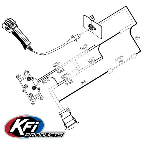
Watch to the end to fing out about the upcoming contest with some pretty great prizes. A simple quick walkthrough on wiring up a 7 pin DPDT "Winch" switch. ... Place a yellow wire from the toggle switch and yellow wire from Rocker Switch into the wire splice, fold the place clip over itself, and snap closed. Repeat for the green and red wires. Finishing Installation Confirm that the winch clutch is disengaged. With the ignition switch, OFF, press Rocker switch to "OUT"—winch should not operate. winch rocker switch wiring diagram - You will need an extensive, professional, and easy to know Wiring Diagram. With such an illustrative guidebook, you'll have the ability to troubleshoot, prevent, and complete your tasks easily.
Winch switch wiring diagram. According to earlier, the traces at a Warn Winch Wiring Diagram signifies wires. Sometimes, the cables will cross. However, it does not imply link between the cables. Injunction of two wires is generally indicated by black dot at the intersection of 2 lines. There'll be principal lines which are represented by L1, L2, L3, and so on. A winch solenoid wiring diagram can help out in this stage, showing you the motor's design. The diagram will help in a later stage, where you need to label your cables and terminals. You can get the pictorial representation from the manufacturer or other mechanics with experience in your winch type. Step 2: Put The Winch In Free Spool Mode Winch Relay Wiring Diagram – Warn Winch Wiring Diagram Solenoid. Wiring Diagram comes with a number of easy to follow Wiring Diagram Instructions. It really is supposed to aid all the typical person in building a correct system. These directions will be easy to understand and apply. As stated earlier, the traces at a 12 Volt Winch Solenoid Wiring Diagram represents wires. At times, the cables will cross. But, it does not imply connection between the wires. Injunction of two wires is usually indicated by black dot at the junction of two lines. There will be primary lines which are represented by L1, L2, L3, and so on.
This switch is simple to install, product comes with a wiring diagram which makes it easy to wire the jumper wires in two seconds. Winch switch. Premium Jumper ... So if you put your switch in, and the IN button is making the cable go OUT, just swap the 2 colored wires around and that will fix it. Usually these 3 wires are hanging off that winch contactor....and you could have mounted it anywhere! EDIT: My wiring is based on YOU having a rocker switch included with your winch. There are two things that will be present in any Winch Wiring Diagram. The first element is symbol that indicate electrical element from the circuit. A circuit is generally composed by numerous components. The other thing you will locate a circuit diagram could be traces. Lines in the diagram show how every element connects to one another. There where so many complicated different color wires and harnesses that made a big tangled mess. I cut out the "remote" switch and some other wiring BS tha...
Spade Wiring 1 “Winch In” indicator light 2 Connect wire from a switched power source 3 “Winch Out” indicator light 4 To Solenoid; “Winch In” 5 Connect wire from a switched power source 6 To Solenoid; “Winch Out” 7 Connect negative “-” wire from Battery or Frame 7 6 2 1 3 4 5 2753 Michigan Road • Madison, Indiana 47250 ... 3 way winch toggle switch wire diagram. As shown below rocker switches have 3 electrical connections. The first way of wiring uses a couple of Two-Way Light Switches with a three wire control 3 Wire Control. A wiring diagram is a simplified standard pictorial representation of an. How To Wire A 3 Way Switch Wiring Diagram Dengarden. Feb 13, 2019 · Winch Rocker Switch Wiring Diagram – 4 pin winch rocker switch wiring diagram, 7 pin winch rocker switch wiring diagram, atv winch rocker switch wiring diagram, Every electrical structure is made up of various distinct parts. Each component ought to be placed and connected with different parts in specific manner. Take a clear look at the diagram, and attach the wires to the different terminals of the switches. The red-colored wire connects with the positive end of the battery from the solenoid box. Now connect the black-colored wire to the winch post from the solenoid box. Use the extension cable and attach it with the battery's negative post.
Wiring Diagram Mom Winch 1 – STV Motorsports Las Vegas
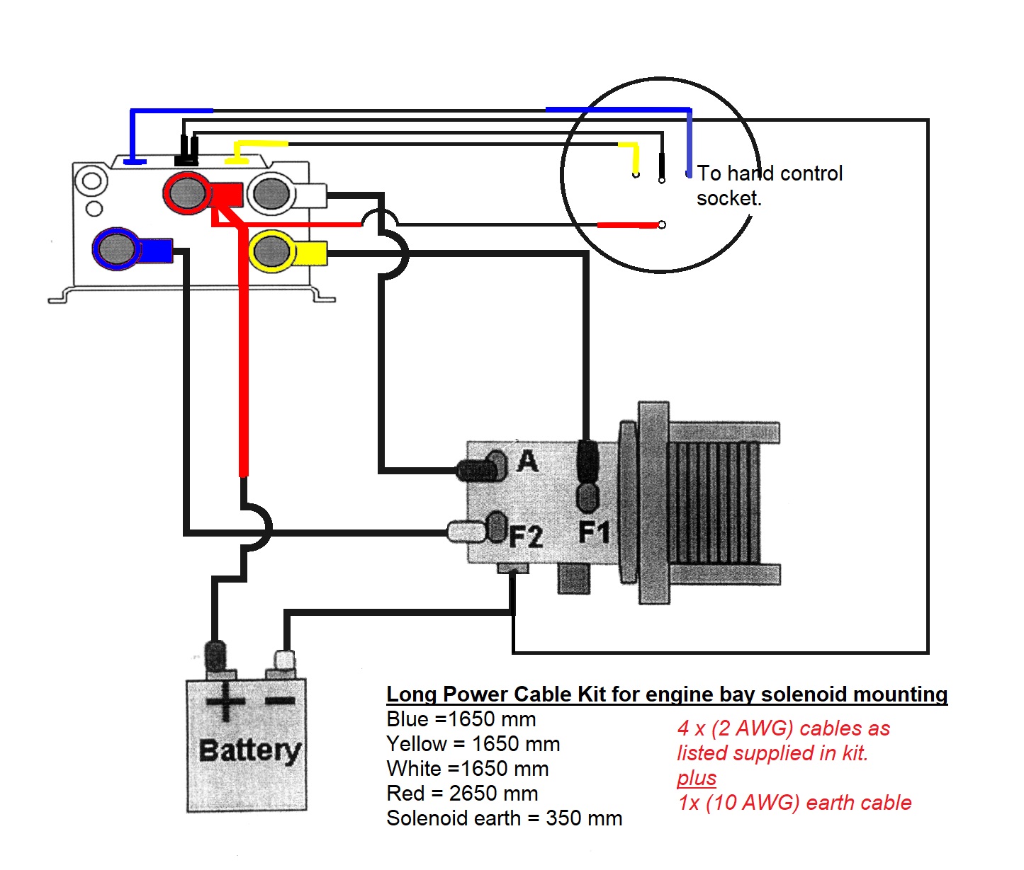
Badland APEX 12000 Winch Wiring Diagram According to the wiring diagram below, attach the black/red/yellow cable from the solenoid box to the winch. Attach the red cable from the winch to the disconnect switch (circuit breaker), and from the circuit breaker, attach the cable to the battery’s positive ends.

Winch cab wiring/switches/remote controller - Modified ...
Step 1 Run the positive and negative motor wires from the winch to the solenoid. Fasten these wires to the correctly labeled terminals on the solenoid by backing off the terminal nuts and securing the ring connectors over the terminal bolts. Tighten the terminal nuts back down. Step 2

Buy WATERWICH 12V 250A Winch Solenoid Relay Contactor+2pcs ...
Wire the trailer-side quick disconnect to the winch. A wiring diagram usually gives information concerning the loved one setting and also arrangement of tools and. Connect winch battery and remaining switch wiring to your contactor using the alternate wiring diagram on Pg. The diagram offers visual representation of a electrical arrangement.
Dash Rocker Switch KIT - KFI ATV Winch, Mounts and Accessories
Dpdt Momentary Winch Switch Wiring Diagram 19.08.2018 3 Comments Functions like two separate SPDT switches operated by the same actuator. switch diagrams illustrate the most common types of toggle and rocker switch. Nilight Momentary Laser Rocker Switch 7Pin Winch In Winch Wiring Harness .

Buy AC-DK 4500 lb Winch Steel Wire Electric Winch Kit, 12V ...
winch wiring diagram – You will want an extensive, professional, and easy to comprehend Wiring Diagram. With such an illustrative guide, you are going to be able to troubleshoot, prevent, and full your projects with ease. Not just will it help you achieve your required final results faster, but additionally make the whole method less difficult for everybody.

12vdc 6 post winch solenoid - DoItYourself.com Community Forums
winch rocker switch wiring diagram - You will need an extensive, professional, and easy to know Wiring Diagram. With such an illustrative guidebook, you'll have the ability to troubleshoot, prevent, and complete your tasks easily.

Mictuning Winch Switch Install
Place a yellow wire from the toggle switch and yellow wire from Rocker Switch into the wire splice, fold the place clip over itself, and snap closed. Repeat for the green and red wires. Finishing Installation Confirm that the winch clutch is disengaged. With the ignition switch, OFF, press Rocker switch to "OUT"—winch should not operate.

Wiring a momentary DPDT switch | JKOwners Forum
Watch to the end to fing out about the upcoming contest with some pretty great prizes. A simple quick walkthrough on wiring up a 7 pin DPDT "Winch" switch. ...

Badland Winches Parts Wiring Diagram (For All Models)
WARN winch in cab controls. | IH8MUD Forum
Rocker switch HELP | Kawasaki Teryx Forum

5pin winch wiring in cab help. | Pirate 4x4
How To Wire A Winch With A Toggle Switch

Traveller Wireless Control With Big Emitter SKU: 117230799 ...
5 Pin Winch Controller In-Cab Wiring | Jeep Wrangler TJ Forum
Winch wiring kit

SOLVED: I have a relay wiring problem - Fixya

Smittybilt Winch Controller Connector? | Second Generation ...
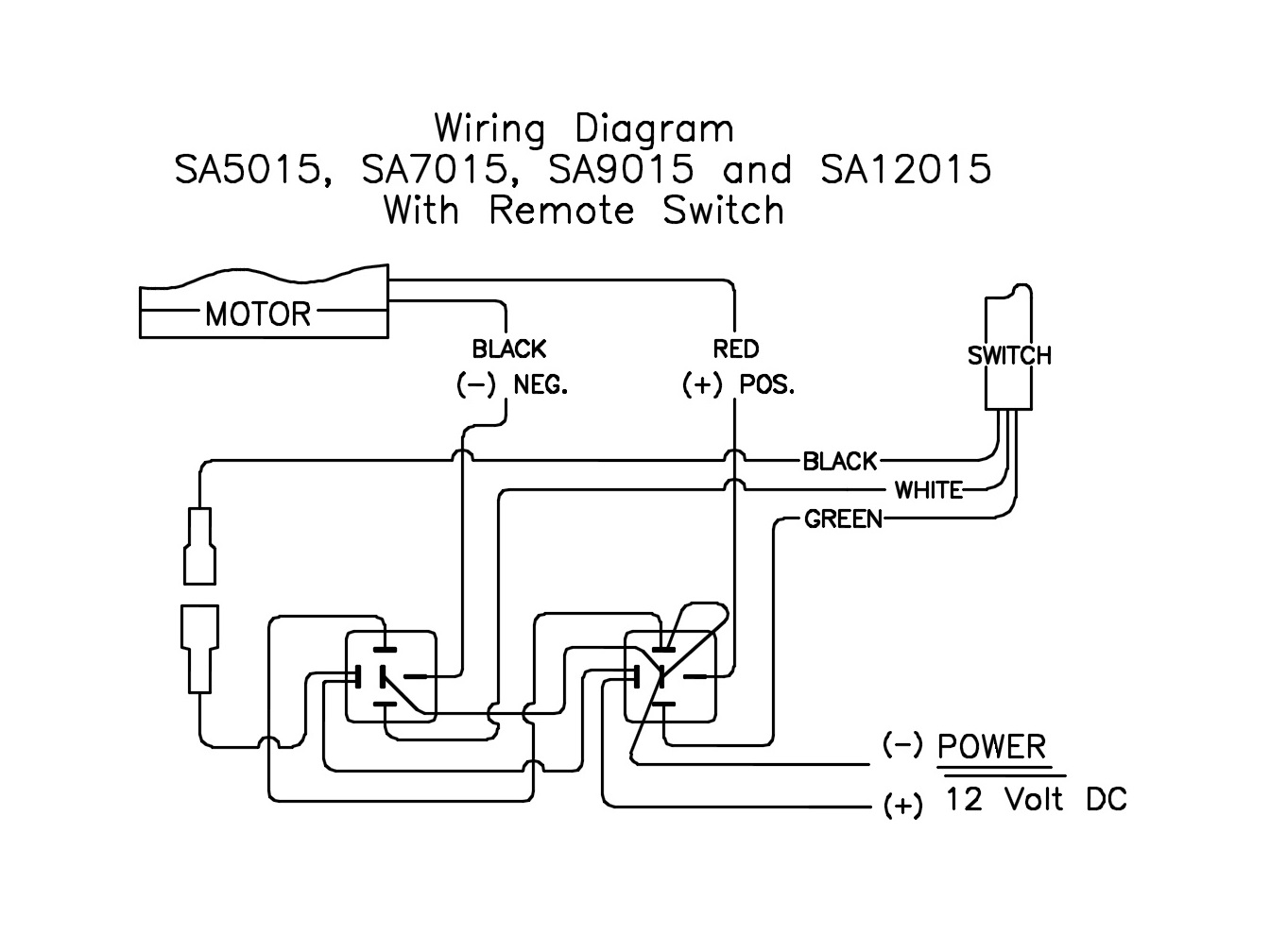
12 Volt DC Electric Winches with Remote Switch ...
Warn Winch cab switch install question | Tacoma World
Rocker switch wiring issue | Polaris RZR Forum - RZR Forums.net

Amazon.com: Nilight - 90001B LED Light Bar Rocker Switch 5Pin ...

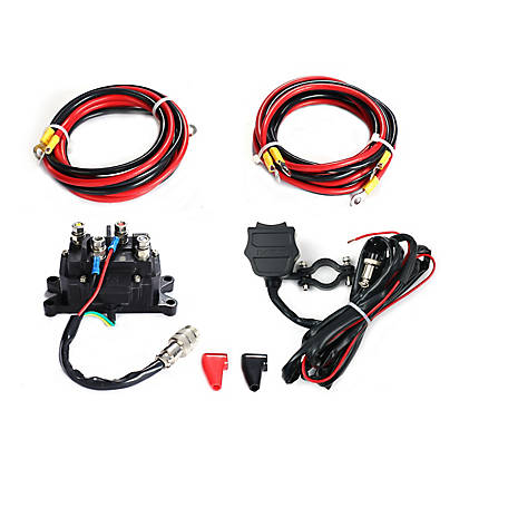
WATERWICH WATERWICH 2pcs Wireless Winch Remote Control Kit 12V Recovery Switch Universal for Truck Jeep ATV SUV
Momentary Winch Switch Wiring

In Dash Winch Control - JK-Forum.com - The top destination ...
Winch Switch Wiring | Yamaha Grizzly ATV Forum

Badland Winches Parts Wiring Diagram (For All Models)
Help wiring a winch 7 pole dash switch | Polaris RZR Forum ...

Nilight 7-Pin Momentary Laser Rocker Switch Winch In/out 20A/12V 10A/24V (Blue)

Warn Atv Winch Solenoid Wiring Diagram | Winch solenoid ...

Rocker switch for winch | Yamaha Wolverine Forum

Warn Mini-Rocker Control Switch - 64851

Factory Winch switch rocker wiring | Wildcat Forum
Traveller Control Set For ATV / UTV Winch
5 Pin Winch Controller In-Cab Wiring | Jeep Wrangler TJ Forum

WARN 99897 ATV Lighted Rocker Switch Dash Control Conversion Upgrade Winch Kit | eBay
In-Cab Winch Control Wiring (From Basic to Warn Zeon) | Jeep ...
Momentary Winch Switch Wiring
0 Response to "38 winch switch wiring diagram"
Post a Comment