41 the engager breakaway system wiring diagram
Hopkins 7 Blade Trailer Connector Wiring Diagram One of the most hard automotive repair tasks that a mechanic or fix shop can acknowledge is the wiring or rewiring of a cars electrical systemThe misery truly is that every car is different. Hopkins 7 pin trailer plug diagram. Recommended use with 47295 and 47285. Review of Hopkins The Engager HD Break-Away System. I was a disappointed with this product for a few reasons. The case is not sealed against water ingress and the electronics is a simple diode charger with battery charge state monitor. In addition the electronics has no protection whatsoever.
Assortment of delco car stereo wiring diagram. A wiring diagram is a simplified standard photographic representation of an electrical circuit. It reveals the elements of the circuit as simplified forms and the power as well as signal connections in between the tools. Delco wire harness diagrams 1 2 3. 16220765 made in usa.

The engager breakaway system wiring diagram
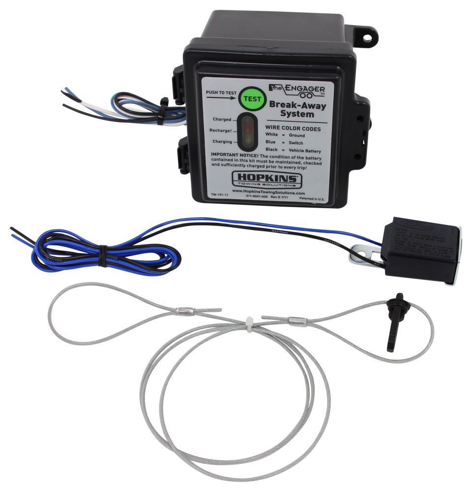
Jun 20, 2019 · The Engager Breakaway System Wiring Diagram – wiring diagram is a simplified customary pictorial representation of an electrical circuit. It shows the components of the circuit as simplified shapes, and the talent and signal friends amid the devices. Hopkins 20099 Engager LED Test Break Away System with Battery Meter. JJThe Engager Break-Away System is designed to bring trailers safely to a stop by activating electric brakes, should a trailer be disconnected while driving. This type of safety system is required in most states on trailers rated over 3,000 Lb. GVW. This Engager model is a front mount unit with tester. Carlisle Braking Systems does not recommend using this product on Disc Brakes. "There is a possibility of the brakes not releasing completely, resulting in damage to the brake system." Replacement Break-Away Pin and Cable Available, Part No. 20051
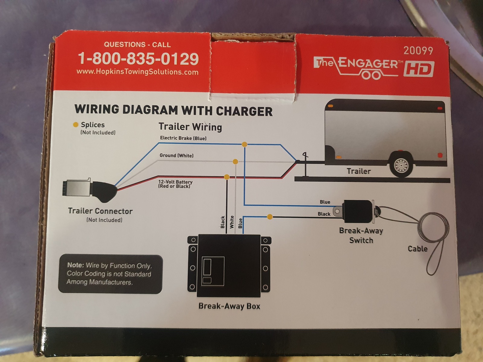
The engager breakaway system wiring diagram. Here, we have the new Engager Breakaway System with charger and battery. We have the pre-installed wires, our ground, power, and break-V.Jan 9, 2015 · Rating: 4.8 · 452 reviews · $49.26 · In stock You Save $23.39! The Engager Breakaway System features a clamshell-style battery box with built-in battery meter to verify battery charge. For use on 1 or 2 axle trailers. Includes side-mount battery box, 5-amp battery, charger, breakaway switch with 7" leads and hardware. Breakaway kit exceeds D.O.T. regulation 393.43 (d) Hopkins Engager Push-To-Test Trailer Breakaway Kit with Built-In Battery Charger - Top Load ... I have attached a wiring diagram you should use below. Rating: 4.8 · 452 reviews · $49.26 · In stock Break-Away Box: SEE WIRING DIAGRAMS ON REVERSE SIDE ... Screws 20400, 20401 (3 with 20099, 4 with 20400) The Engager™ Break-Away System is designed to bring trailers safely to a stop by activating electric brakes, should a trailer be disconnected while driving. This type of safety system is required in most states on trailers rated over ...
Hopkins offers a variety of towing solutions including vehicle wiring kits, adapters, vehicle and trailer connectors, breakaway systems and much more. Today, more than 40 percentage of retail category sales are generated from Hopkins innovations. The Hopkins Engager Break Away System changes the way you protect your trailer investment. 1998 Toyota Corolla Headlight Wiring Diagram. White Electrical Wire. 2 Way Fan. Ceiling Fan Light Fixture Wiring. The Engager Breakaway System Wiring Diagram. Post navigation. 30a Dryer Receptacle. 2001 Polaris Sportsman 500 Ho Wiring Diagram. Leave a Reply Cancel reply. Your email address will not be published. The Engager™ Break-Away System is designed to bring trailers safely to a stop by activating Follow “Wiring Installation”. WIRING DIAGRAM ON BACK. WIRING INSTRUCTIONS: 1. Splice one blue wire of the Break-Away Switch to the electric brake wire coming from the trailer side connector (A - see diagram on . I have all of the wires hooked up except the black wire on the switch. connect to the blue wire from the break away box, as shown in the provided diagram. Hopkins Engager Push-To-Test ... Apr 23, 2021 · Troubleshoot Trailer Wiring - The Engager Breakaway System Wiring Diagram - How to troubleshoot trailer wiring issues or problems. April 23, 2021 During one of my towing excursions the plug was pulled from the trailer due to it being dark out and me not noticing that the wiring wasn't.
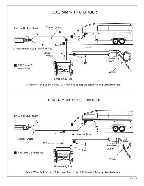
The Engager Break-Away System is designed to bring trailers safely to a stop wire coming from the trailer side connector A - see diagram. 1-4 Wire the first 4 pins White Brown Yellow Green just like the 4-pin connector above. These updates provide information on how to safely operate and maintain your Carry-On Trailer. Jul 12, 2018 · Tow Ready Trailer Break Away Kit Installation - Video Replacement Battery for Hopkins Engager Trailer Break Away System. The Engager™ Break-Away System is designed to bring trailers safely to a stop wire coming from the trailer side connector (A - see diagram on next page). Test your Break-Away Kit before each outing as described in Step 5 of the wiring . How to Wire Break Away Switch on Hopkins Engager Break Away System. The following diagram shows a typical wiring configuration for a Hopkins breakaway kit with a battery charger. Some other manufacturers have similar ... The Engager™ Break-Away System is designed to bring trailers safely to a stop by activating electric brakes, should a trailer be disconnected while driving. This type of safety system ... WIRING DIAGRAM ON BACK CABLE INSTALLATION FIG 1 FIG 2 FIG 3 CABLE CABLE CABLE BREAK-AWAY SWITCH BREAK-AWAY SWITCH BREAK-AWAY SWITCH BUMPER CLEVIS SAFETY ...
The Trailer Breakaway System is designed to bring a trailer to a safe stop by activating the electric brakes on the trailer, should the trailer be disconnected from the tow vehicle while driving. You must have operational electric brakes on the trailer, the 12 volt battery must be charged& the switch cable must be attached to the vehicle.
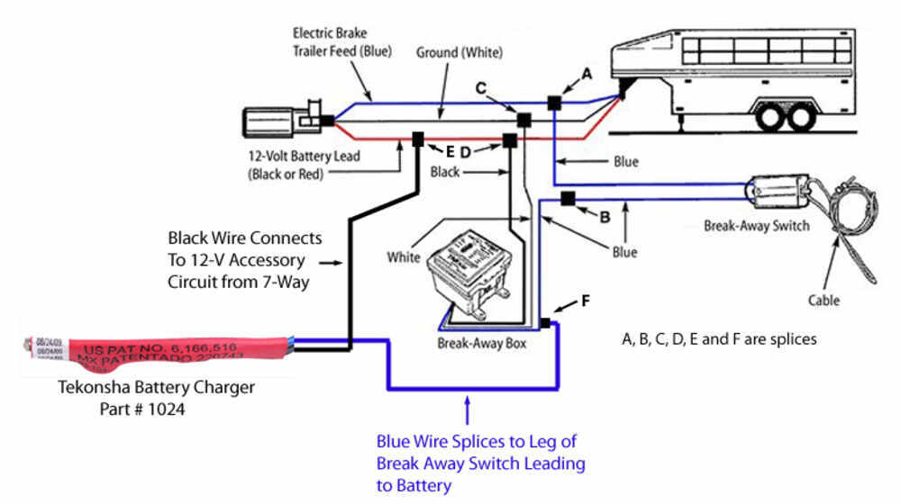
The black wire on the Engager breakaway system # 20099 will be connected to a 12v auxiliary power wire coming off of the trailer connector. This wire is typically the number 4 black terminal in the 7-way connector, but you will need to test to determine if your plug is wired this way, as the auxiliary function can also be located on the center pin.
Click for more info and reviews of this Hopkins Trailer Breakaway Kit:https://www.etrailer.com/Trailer-Breakaway-Kit/Hopkins/20400.htmlCheck out some similar...
Aug 12, 2016 — Wiring Diagram for Trailer Breakaway Kit On this page (typically below the product links) there is a helpful link section that will have the ...1 answer · Top answer: I have attached the installation instructions for the Hopkins Engager Trailer BreakAway Kit, part # 20099. This kit includes a charger and an LED tester ...
Polaris Scrambler 90 Wiring Diagram - wiring diagram is a simplified standard pictorial representation of an electrical circuit. It shows the components of the circuit as simplified shapes, and the capability and signal links along with the devices. A wiring diagram usually gives information just about the relative point and concord of ...
Trailer Breakaway Wiring Diagram – People comprehend that trailer is a vehicle comprised of quite complicated mechanisms. This car is designed not only to travel 1 location to another but also to take heavy loads. This guide will be talking trailer breakaway wiring diagram.Which are the advantages of knowing these understanding?
the engager breakaway system wiring diagram new wiring diagram for trailer breakaway kit and redline trailer of the engager breakaway system wiring diagram wiring diagram for electric brakes on a trailer new stock refrence lovely of Example Full We collect lots of pictures about Tap Breakaway Kit Wiring Diagram and finally we upload it on our ...
The black wire from the break away switch will connect to the blue wire from the break away box, as shown in the provided diagram. By 'brake wires' I'm assuming you're speaking of the wires connected to the brake magnets on your brake assemblies. One wire exiting the brake magnet could connect to the brake output circuit, usually a blue wire ...
I also attached an install video that shows the kit installed as well as a diagram for trailer breakaway wiring as well. The white wire is the ground wire.1 answer · Top answer: On this page (typically below the product links) there is a helpful link section that will have the install instructions fo the Hopkins Breakaway kit ...
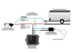
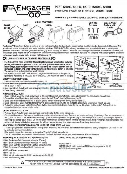
1. Splice one blue wire of the Break-Away Switch to the electric brake wire coming from the trailer side connector (A - see diagram on next page). 2. Connect other blue wire of Break-Away Switch to the blue wire (labeled “Brake”) from the Break-Away box (B). (Note: Blue wires are interchangeable on the Break-Away Switch.) 3.
Jan 12, 2018 · Follow "Wiring Instructions". WIRING INSTRUCTIONS: BREAK-AWAY SWITCH FIG. 2 BREAK-AWAY SWITCH SAFETY CHAIN POCKET BUMPER CLEVIS FIG.I CABLE PIN BREAK-AWAY SWITCH FIG. 3 CABLE INSTALLATION 1. Splice one blue wire of the Break-Away Switch to the electric brake wire coming from the trailer side connector (A - see diagram on next page). 2. The Engager is designed to activate the trailer brakes in the event the trailer is separated from the towing vehicle. Trailer break-away kits are legally ...
Break-Away System for Single and Tandem Trailers ... BAIO-250 Break-Away Kit, Engager, 5 A/H Battery, Charger, Switch, LED Test Lights, Top Open BAI 0-150 ... BA01-020 Battery, 12V, 5 A/H Sealed, Rechargeable BA02-020 SEE WIRING DIAGRAMS ON PAGE 2 . DIAGRAM WITH CHARGER DIAGRAMA CON EL CARGADOR DIAGRAMME AVEC CHARGEUR Blue / Azul / Bleu
Hopkins 20099 Engager LED Test Break Away System with Battery Meter . JJThe Engager Break-Away System is designed to bring trailers safely to a stop by activating electric brakes, should a trailer be disconnected while driving. This type of safety system is required in most states on trailers rated over 3,000 Lb. GVW.
The Engager Breakaway System Wiring Diagram. The black wire on the Engager breakaway system 20099 will be connected to a 12v auxiliary power wire coming off of the trailer connector. Wiring Directions for Hopkins Engager Push-to-Test Trailer Breakaway Kit.
Wiring diagram for trailer breakaway kit & Redline Trailer from the engager breakaway system wiring diagram , source:color-castles.com. So, if you desire to acquire these incredible pics about (Inspirational the Engager Breakaway System Wiring Diagram. ), press save link to save these pics to your laptop. They’re available for download, if ...
The Engager™ Break-Away System is designed to bring trailers safely to a stop by activating electric brakes, should a trailer be disconnected while driving. This type of safety system ... WIRING DIAGRAM ON BACK CABLE INSTALLATION FIG 1 FIG 2 FIG 3 CABLE CABLE CABLE BREAK-AWAY SWITCH BREAK-AWAY SWITCH BREAK-AWAY SWITCH BUMPER CLEVIS SAFETY ...
This Engager model is a front mount unit with tester. Carlisle Braking Systems does not recommend using this product on Disc Brakes. "There is a possibility of the brakes not releasing completely, resulting in damage to the brake system." Replacement Break-Away Pin and Cable Available, Part No. 20051
Hopkins 20099 Engager LED Test Break Away System with Battery Meter. JJThe Engager Break-Away System is designed to bring trailers safely to a stop by activating electric brakes, should a trailer be disconnected while driving. This type of safety system is required in most states on trailers rated over 3,000 Lb. GVW.
Jun 20, 2019 · The Engager Breakaway System Wiring Diagram – wiring diagram is a simplified customary pictorial representation of an electrical circuit. It shows the components of the circuit as simplified shapes, and the talent and signal friends amid the devices.










![[DIAGRAM] The Engager Hopkins Wiring Diagram FULL Version ...](https://images.etrailer.com/static/images/pics/r/i/rid448164_r1_800.jpg)

0 Response to "41 the engager breakaway system wiring diagram"
Post a Comment