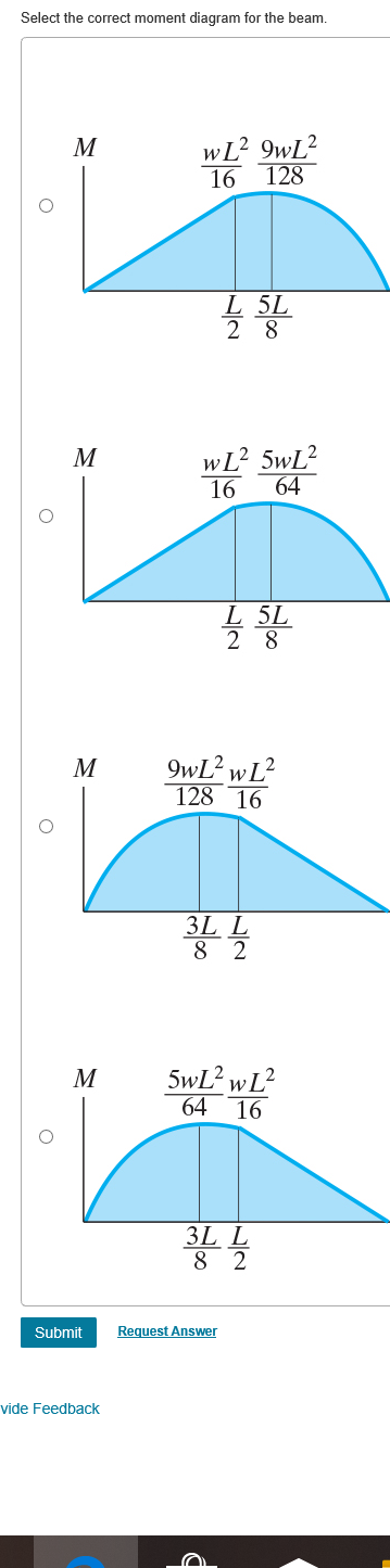
39 select the correct shear diagram for the beam. (figure 1)
Using the SkyCiv Load Generator in AS/NZS 1170.2 (2021) Wind Load Calculations for Solar Panels To calculate the wind load pressures for a structure using SkyCiv Load Generator, the process is to define first the code reference. From there, the workflow is to define the parameters in Project Tab, Site Tab, and Building Tab, respectively. Draw the shear and moment diagrams for the beam shown in Fig. 6–4a. ... (These relationships are developed in the next section as Eqs. 6–1 and 6–2.).
Answer to: Select the correct shear diagram for the beam. (Figure 1) By signing up, you'll get thousands of step-by-step solutions to your homework...
Select the correct shear diagram for the beam. (figure 1)
That means that a team of three will have six testable trusses completed at the end of the building phase. Your overall truss must be 8-12 inches (20-30 cm) long, 3-5 inches (7.5-12.5 cm) tall and 3-5 inches (7.5-12.5 cm) wide. You may use up to 35 Popsicle sticks per truss, no more. You are permitted to use fewer. Figure 1 shows a column of fatty tissue, determine the strain in each of the three regions. Figure 1. A column of fatty tissue. Associated Activities Applying Hooke's Law to Cancer Detection - Student groups explore Hooke's law by collecting displacement data for springs with unknown spring constants by adding various masses of known weight ... 1 answer. 1- A saturated soil sample has a volume of 190 cm and a weight of 3.43 N. Determine its void ratio, porosity, water content and unit weight (Gs = 2.7). 2- A moist soil has a total volume of 7.08 x 10. 1 answer. Dessin (1) Analyze the following frame.
Select the correct shear diagram for the beam. (figure 1). Transcribed image text: Consider the beam shown in (Figure 1). Choose the correct shear diagram for the beam. Follow the sign convention V - - w(6Lx + ...1 answer · Top answer: Please ask your doubts in the... The cantilever beam shown in Figure Q3a is subjected to a uniformly distributed load of w1 = 2.8kN/mandapointloadofP1 =5kN. (a) Draw the shear force diagram, and label the location and magnitude of th Question 3 The cantilever beam shown in Figure Q3a is subjected to a uniformly distributed load of W1 = 2.8 kN/m and a point load of P. = 5 kN ... The "base shear force" formula is taken from EC-8 4.3.3.2.2(1)P. The "base shear force" is nothing else than the total seismic force of inertia that acts between the ground and the structure, and it can be distributed in two ways: Predicting clay sensitivity is important to geotechnical engineering design related to clay. Classification charts and field tests have been used to predict clay sensitivity. However, the imbalanced distribution of clay sensitivity is often neglected, and the predictive performance could be more accurate. The purpose of this study was to investigate the performance that extreme gradient ...
neutral stress examplesfor sale by owner nellysford, va. The Power & IT Company ... you how to graphically draw a shear and moment diagram for a beam. In general the process goes like this: 1) Calculate support reactions ... (Figure 1) w L 3L 8 L wL 4 w L 5L L х 2 wL V w L 5L L х 2 ЗwL V wL 3L ЗwL 8 Select the correct moment diagram for the beam w L2 9WL2 128 16 L 5L 2 8 wL2 5WL2 М ... 12.12.2020 ... Note 1 - The curve you choose from the drop-down is only a pictorial representation of a real quadratic/cubic curve. The equation of this curve ...
Normal positive shear force convention (left) and normal bending moment convention (right). This convention was selected to simplify the analysis of beams. RB = -1 kN. (For member BC). So SFD will be. So For member AC, SF will be. For section AP, ... For the beam shown, choose the correct maximum shear loading and moment loading on the cross-section in the beam. A steel cantilever beam is loaded as shown. The beam is a W18x60. Question: Part A Select the correct shear diagram for the beam (Figure 1) V 2wa o X 2a Figure < 1 of 1 > - Zwa 2wa . Za V wa a 2a -wa V wa x а 2a Part B. Select ...1 answer · Top answer: Optio...
Solved w JÑ Ð’ Select the correct shear diagram for the ...
Assume a maximum slenderness ratio of 60 a) 4.03 b) 3.12 c) 2.24 d) 1.73; Draw the shear and moment diagrams for the beam, and determine the shear and moment throughout the beam as functions of x ...
Drawing Shear and Moment Diagrams Example- Mechanics of Materials and Statics
(Figure 1) wa 2a -wa 2wa 2wa x. 2a -2wa wa -Part B Select the correct moment diagram for the beam. 2a 2a 2a 24. This problem has been solved ...
Problem 9.1 Two beam segments, AC and CD, are connected ...
1 Click K Open on a Project-Specific Basis. 2 On the right-hand side under Derived from building structure open the Detached house - Sections folder, Section 1. 3 Open the shortcut menu of drawing file 1010 and select Source drawing files for section. 4 Click on the drawing files 2, 100, 101, 109, 110, 112, 116, 120 and 129 and click OK to close.
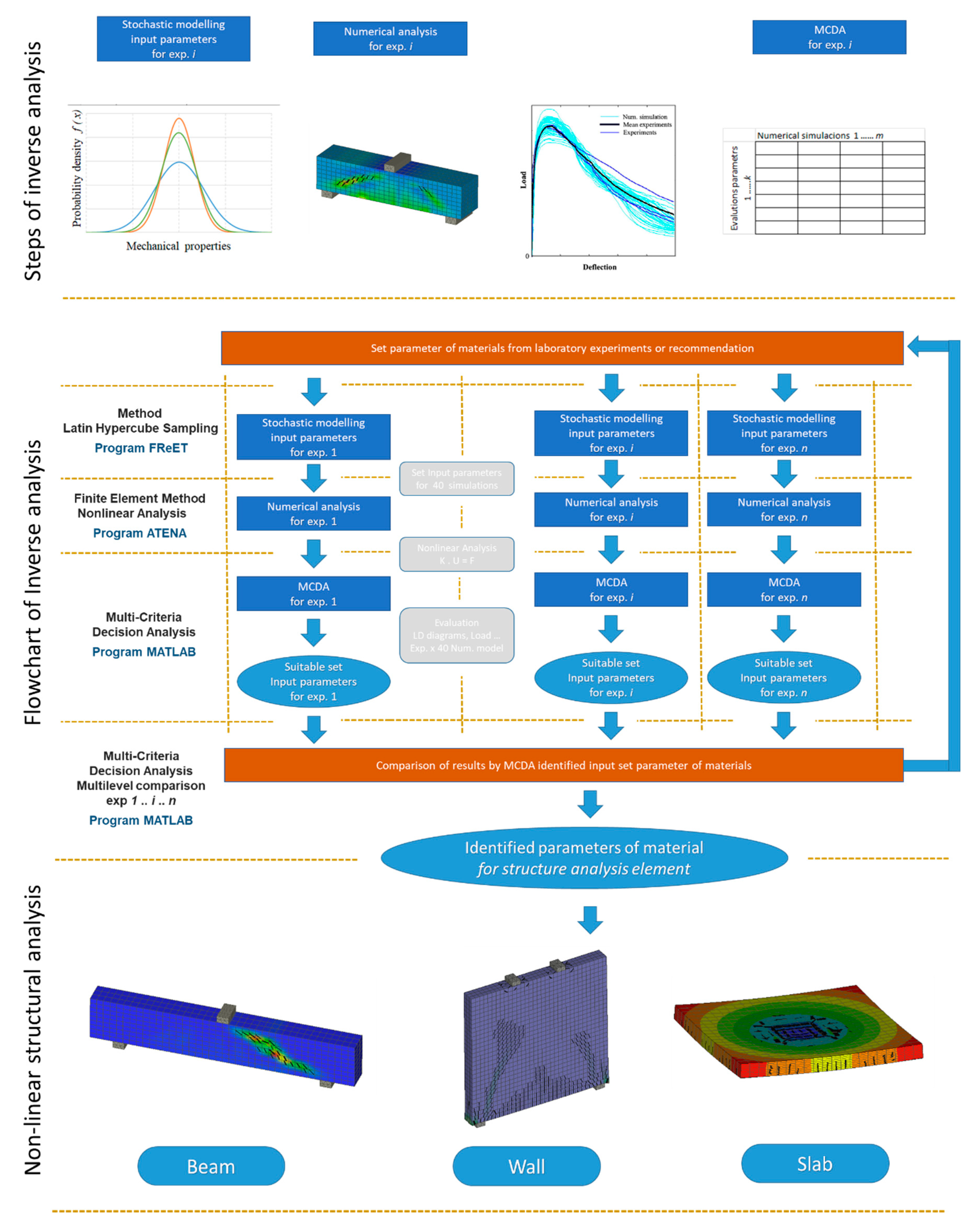
Materials | Free Full-Text | Identification of Fracture ...
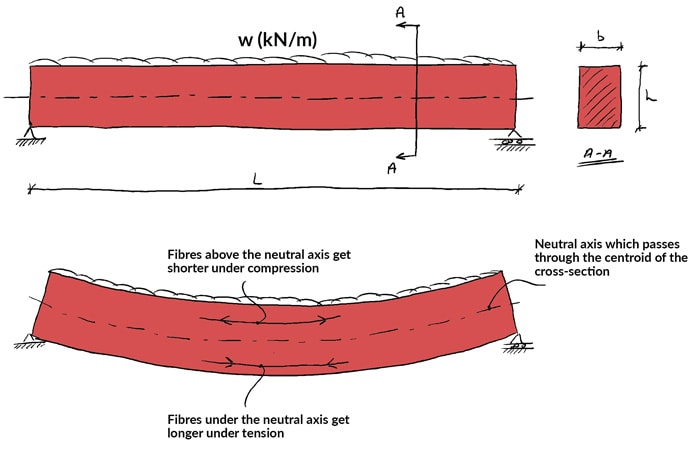
05.03.2021 ... Fig. 4.1. Internal forces in a beam. 4.2 Basic Definitions. 4.2.1 Normal ... The bending moment diagram of the beam is shown in Figure 4.5d.

draw the shear and moment diagram, Part A Draw the shear ...
The paper mentions a shearing test, shear displacement and shear force, but then only provides experimental data of a crushing test, i.e. crushing force (pressure). Figure 4 has crushing force on the Y axis and shear force on the Figure caption. The x axis is confusing (displacement ) -1 to 0 to 1. Only a stroke of 75 mm is mentioned in section ...
The Ultimate Guide to Shear and Moment Diagrams ...
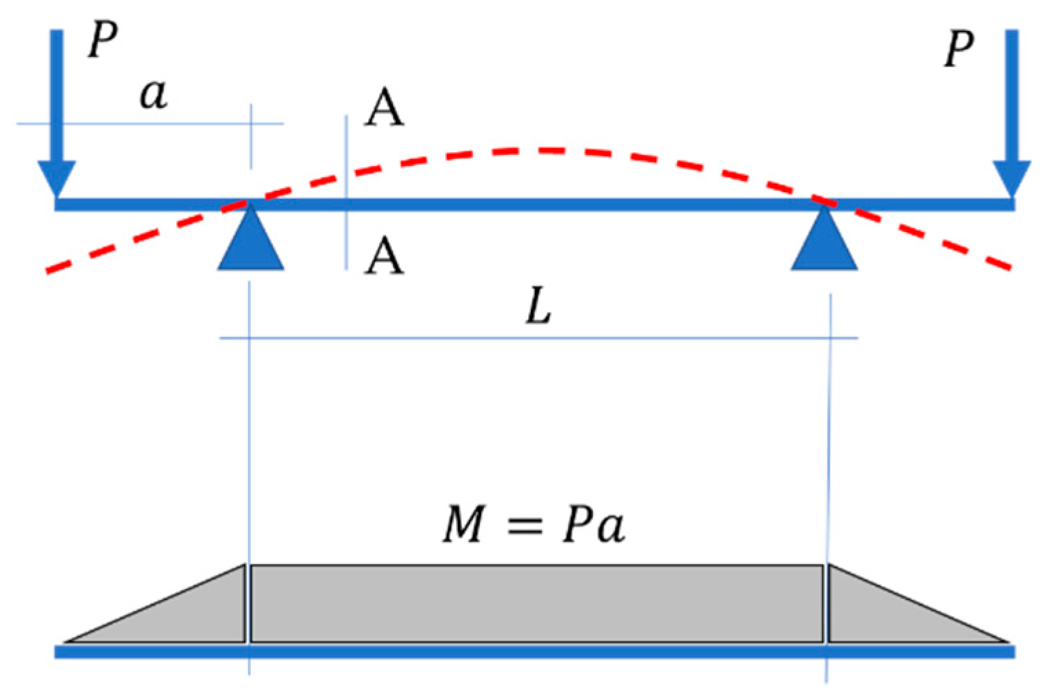
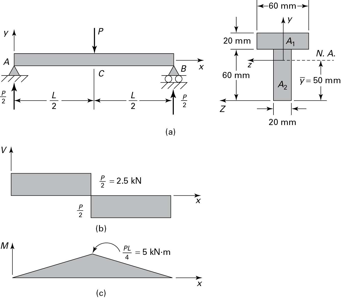
A simply supported beam is loaded by two equal concentrated loads, symmetrically placed as shown in Figure 1. The shear and moment diagrams for this configuration are also shown in the figure. The shear force magnitude, V, is equal to the applied concentrated load, P. The maximum moment, M m a x, occurs between the two loads and is equal to P a.
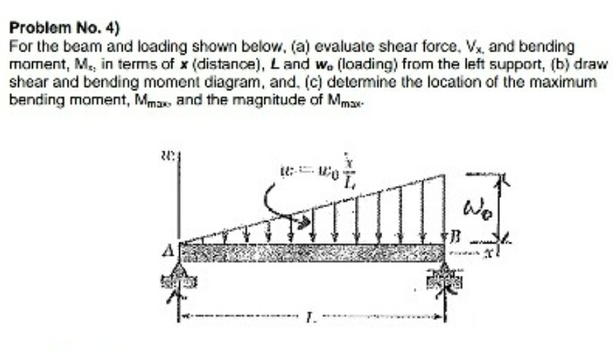
Solved) - For the beam and loading shown below, (a) evaluate ...
point shown in Fig.a will be used to write the shear and moment equations of the beam. *6–4. Draw the shear and moment diagrams for the canti- lever beam.
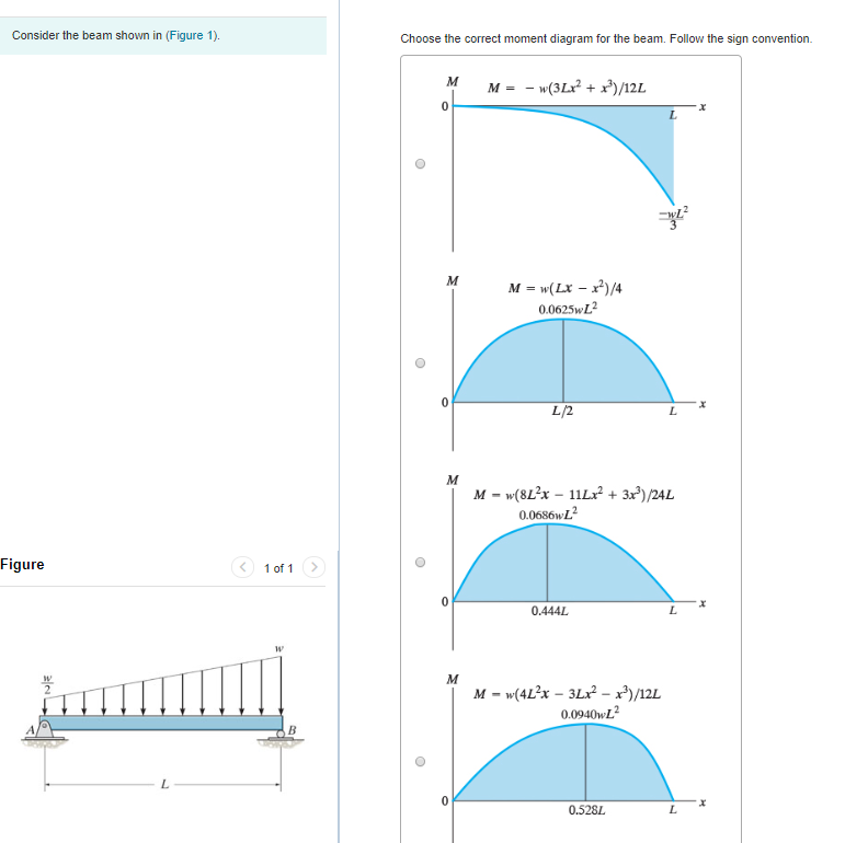
Solved Choose the correct shear diagram for the beam. Follow ...
I’m trying to determine what the shear and moment diagrams of a bolt in single shear look like. Before anyone says it, I know that it’s rare that a bolt will ever fail first in bending, and this is something that typically isn’t even checked for. Anyway, I’ve assumed that the bolt is essentially a beam cantilevered at one end and guided at the other (guided end only allows vertical translation, no rotation). I’ve applied a distributed load acting downward over half the bolt length, and a distri...
Cryogenic electron tomography to determine thermodynamic ...
Look through microlam beam pictures in different colors and styles and when you find some microlam beam that. Then scroll down to see shear force diagrams, moment diagrams. 30' long supported each 6'. This tells you the size of the beam needed to support the porch's roof. 1-1/2 inch (4) 1-3/4 inch (103) 5-1/4 inch (6) Actual Width.
Chapter 4-internal loadings developed in structural members
Part A. Draw the shear diagram for the beam. Follow the sign convention. Part B. Draw the moment diagram for the beam. Follow the sign convention. Figure 1 ...
Materials | Free Full-Text | Analytical Determination of the ...
1 answer. 1- A saturated soil sample has a volume of 190 cm and a weight of 3.43 N. Determine its void ratio, porosity, water content and unit weight (Gs = 2.7). 2- A moist soil has a total volume of 7.08 x 10. 1 answer. Dessin (1) Analyze the following frame.
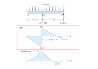
Shear force and bending moment diagram practice problem #4
Figure 1 shows a column of fatty tissue, determine the strain in each of the three regions. Figure 1. A column of fatty tissue. Associated Activities Applying Hooke's Law to Cancer Detection - Student groups explore Hooke's law by collecting displacement data for springs with unknown spring constants by adding various masses of known weight ...

Computerâ€based evaluation of design methods used for a steel ...
That means that a team of three will have six testable trusses completed at the end of the building phase. Your overall truss must be 8-12 inches (20-30 cm) long, 3-5 inches (7.5-12.5 cm) tall and 3-5 inches (7.5-12.5 cm) wide. You may use up to 35 Popsicle sticks per truss, no more. You are permitted to use fewer.
Untitled

Bending moment and shear force diagram of a cantilever beam

Early breast cancer: ESMO Clinical Practice Guidelines for ...

Achromatic terahertz Airy beam generation with dielectric ...
EMI radiation of power transmission lines in... | F1000Research

3D seismic characterization of fractures using elastic P-to-S ...
Solved) - Draw the shear and moment diagrams for the beam ...
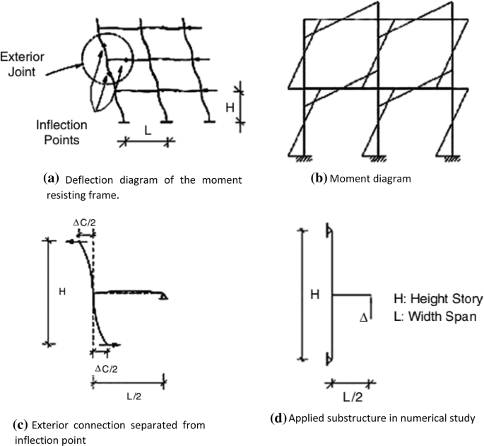
Seismic Behavior of Frames with Bolted End Plate Connections ...
The Ultimate Guide to Shear and Moment Diagrams ...

Analysis of rectangular hollow section trusses
PROBLEM 5.1
HESS - Hydrologically informed machine learning for rainfall ...

8. SHEAR FORCE AND BENDING MOMENT - ppt video online download
5.7 Normal and Shear Stresses | Bending of Beams | InformIT
Mechanics of Materials Chapter 4 Shear and Moment In Beams
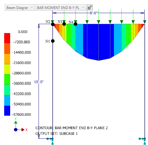
How to understand results in beam and bar elements in Nastran ...
![Solved] The part of the shear force diagram for a beam is ...](https://storage.googleapis.com/tb-img/production/20/06/F4_S.C_Madhu_21.05.20_D%206.png)
Solved] The part of the shear force diagram for a beam is ...
Beam Reactions and Diagrams – Strength of Materials ...
5.7 Normal and Shear Stresses | Bending of Beams | InformIT
Mechanics of Materials Chapter 4 Shear and Moment In Beams

Shear Force Diagram - an overview | ScienceDirect Topics

Why do we calculate STRESS, when we have FORCES?

Applied Sciences | Free Full-Text | Neural Network-Based ...

Beam Reactions and Diagrams – Strength of Materials ...
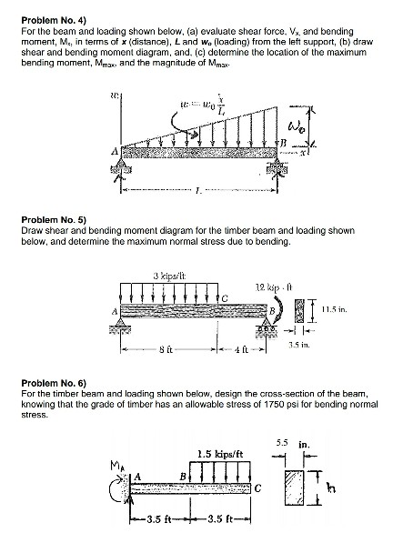
Solved) - For the beam and loading shown below, (a) evaluate ...

Statics 7.61 - Draw the shear and moment diagrams for the beam.
0 Response to "39 select the correct shear diagram for the beam. (figure 1)"
Post a Comment