41 gem remotes wiring diagram
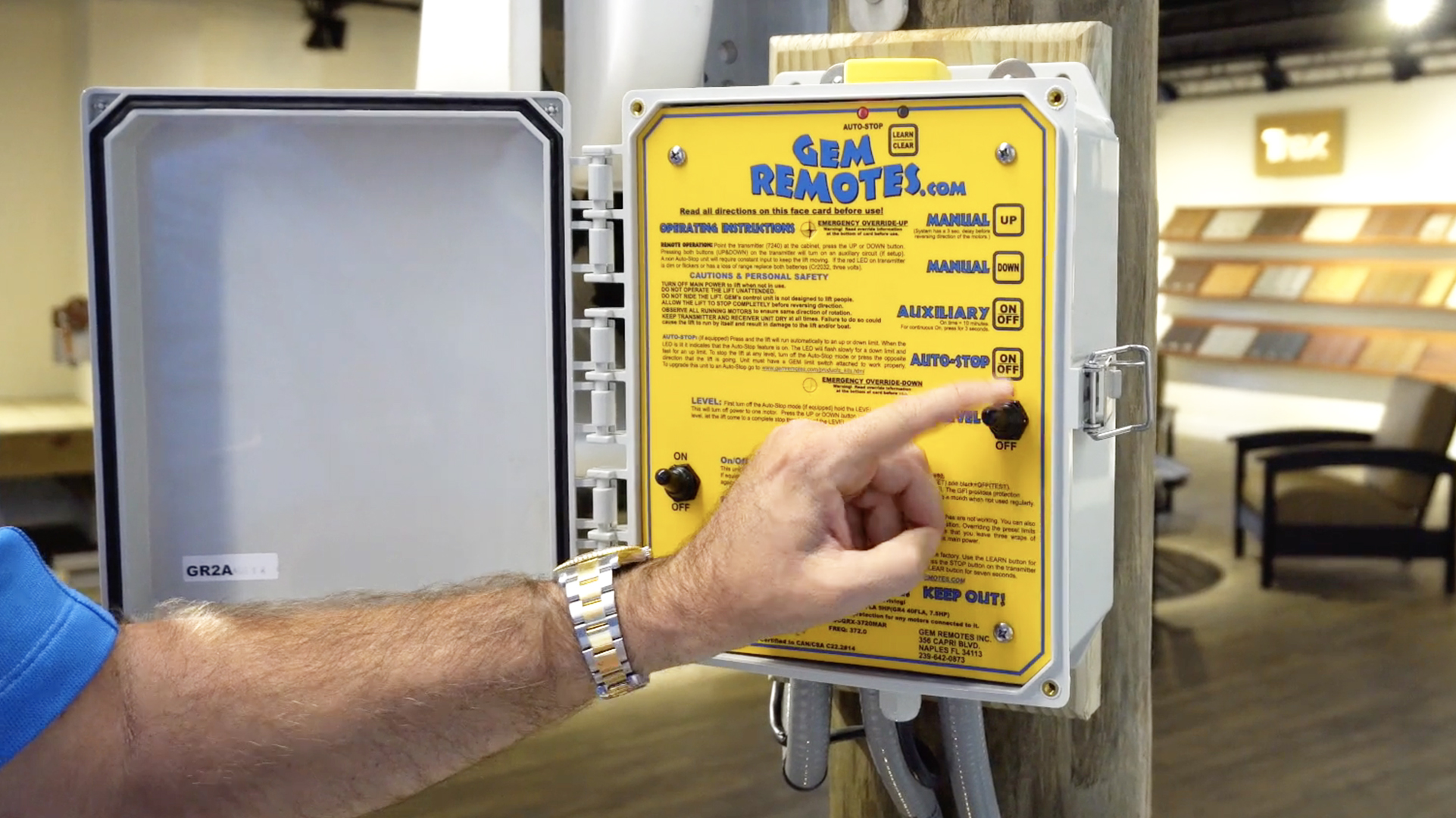
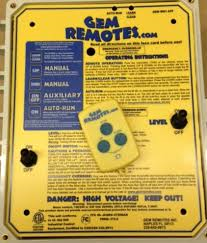
Programming the waterproof Gem Remote that came with your cargo lift is very easy. You need to have the remote transmitter in hand and be at the GEM box on your deck/dock or balcony. You will need to press two buttons, one in the GEM box; the other on the remote transmitter. Find the LEARN button in your GEM box then find the DOWN button on ... GEM REMOTES has been manufacturing boatlift controls since 1985. Based in Naples, Fla., GEM continues to perfect a remote control system which increases the safety and convenience of your boatlifts, davits, hoists or personal watercraft ramps. We infuse all of our products with quality features you will come to expect when you think of us - GEM REMOTES!
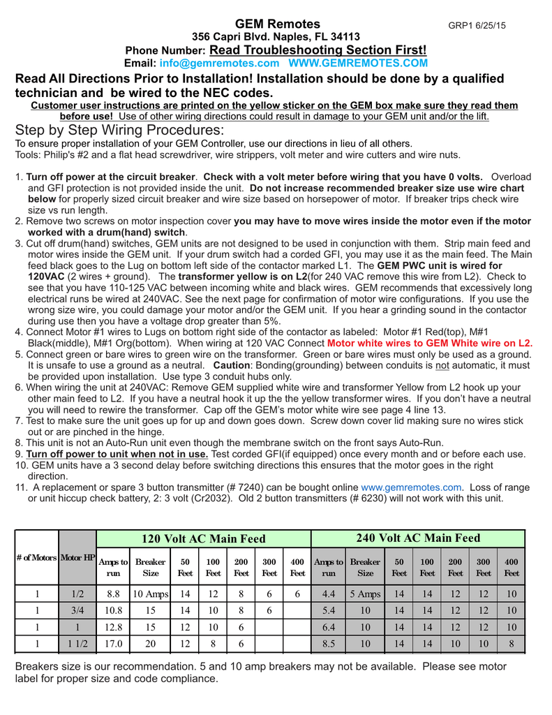
GEM Remotes 356 Capri Blvd. Naples, FL 34113 Phone Number: ... Use of other wiring directions could result in damage to your GEM unit and/or the motor. We have 25 years of experience. We recommend that you read and use the Step by Step Wiring Procedures ... check for that motor diagram on the next page otherwise use the Standard T Numbered Wire

Gem remotes wiring diagram
7. Wiring the motors and the GEM unit at 230VAC: Cap off the GEM White motor wires. These wires are not used at 230VAC. 8. To confirm and/or change motor wiring, open motor covers and configure motor winding wires as shown below. Inspect wires Note: drum switch wire Org might be pre-wired to Motor Blk(T5)*. 7. Wiring the motors and the GEM unit at 230VAC: Cap off the GEM White motor wires. These wires are not used at 230VAC. 8. To confirm and/or change motor wiring, open motor covers and configure motor winding wires as shown below. Inspect wires inside each motor to ensure proper wire connection. Use the motor wire diagrams below. Wiring Diagrams. Century Pool & Spa Motor Manual; Gem Remotes Auto Stop Diagram; Gem Remotes Wiring Diagram; Wire Size Chart; AOS 3/4 HP Open Drip or TENV Motor - 115V/230V Wiring Diagram. 230 Volt Wiring Help - Video; 115 Volt Wiring Help - Video; Collections. Aluminum Mount;
Gem remotes wiring diagram. GEM Remotes: KELS Limit Switch Wiring Diagram will give you all the details you will need to wire this limit switch if you are looking to do it yourself. If you have any questions about this model, you can use the contact feature on the website. We will do our best to answer your question as soon as possible. GEM REMOTES E-DRIVE LIMIT SWITCH INSTRUCTIONS 1. Mount the unit horizontally as shown in the pictures. Note: To prevent water from getting in make sure it is in this orientation. 2. See page 1 for adjustment instructions. Questions? Call GEM 239-642-0873 Bolts for installing KFLS wires to carry 220V, rewire the GEM multitap transformer for 220V, and rewire the motors at 220V. (See 230V wiring diagrams figs. 6 and 7 on the wiring diagram page.) 9. If you experience short range with your remote, or lift hiccups, replace the battery in the remote. Replace battery also if the red light on the remote control is dim or ... GEM Remote Controls. AMS carries several products from GEM remotes including 1, 2, and 4 motor remote controls and more. For more information on GEM Remotes, visit GEMREMOTES.com.
correct place using the switch wiring diagram on page 6. Our diagrams show a 5-wire cable consisting of Black, White, Red, Orange, and Green which is what is used by AMS and is the standard throughout most of the industry. L1 L2 Special Note: GEM Remotes If you are using a GEM remote control instead of a switch, and have How to Wire A Traveller Wireless Remote LD 0 0006 PM 3554 0131 thumbnail D17GF circuit diagram2 We collect a lot of pictures about How to Wire A Traveller Wireless Remote and finally we uplo... Find this Pin and more on wiring diagram by Anisha Rivera. Remote. Grand Cherokee Limited. Auto Start. GEM 4 Motor Remote with Auto Stop. $ 1,226.79. Add to cart. GEM boat lift remotes provide reliable operating control for your boat lift. Purchase one from Boat Lift Warehouse today for smooth operation! Gem Remote Wiring Diagram Download. Variety of gem remote wiring diagram. A wiring diagram is a streamlined conventional photographic representation of an electrical circuit. It shows the parts of the circuit as streamlined shapes, and the power and also signal connections in between the devices. A wiring diagram generally provides details about the relative position…
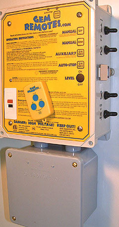
GEM REMOTES. Maybe you're not the person who had your GEM REMOTES installed. If you're a do-it-yourself person, you may want to utilize GEM REMOTES to help you with any problems you may be having. Our service team knows the GEM REMOTES System, and we are more than happy to be of service to you. GEM Remotes 356 Capri Blvd. Naples, FL 34113 Phone Number: ... Use of other wiring directions could result in damage to your GEM unit and/or the motors. We have 30 years of experience. We recommend that you read and use the Step by Step Wiring Procedures before ... AO Smith motors)! If your motor has terminals inside, check for the motor diagram Gems Sensors Instructions, 4700B Standard. Download the Gems Sensors & Controls 4700B Series installation instructions bulletin. Download. Accommodates optional multiple transmitters for the boat lift remote. The control box features a black water-resistant gasket. The control faceplate has raised buttons for operation and one toggle switch that regulates power to the remote. Made by GEM Remotes. Online wiring and troubleshooting guide diagrams for each model. FFC & ETL listed.
GEM Remotes Simplified Wiring Instructions; GEM Auto Stop OEM Installation; GEM GR4 / GR4A OEM Installation; GEM GR2 / GR2A OEM Installation; GEM GR1 / GR1A OEM Installation; GEM Remote Control Owner's Manual; Motor with Brake Wiring Diagram

Gr2 Double Motor Boat Lift Remote Gem Remotes Bh Usa. Classic model boat plans wiring diagram correction motor radio controlled modelling maxwell building standards basic build a simple arduino rc that can borders club boats installation diy electronic sd controller make electronics how to wire an external bec roger s car schematics rct2 handhel control transmitter gr2 double lift remote gem ...
GEM REMOTES has been manufacturing boatlift controls since 1985. Based in Naples, Fla., GEM continues to perfect a remote control system which increases the safety and convenience of your boatlifts, davits, hoists or personal watercraft ramps. We infuse all of our products with quality features you will come to expect when you think of us - GEM REMOTES!
Wiring Diagrams. GEM REMOTE WIRING INSTRUCTIONS. CLICK HERE TO VIEW. 115 VOLTS. GEM REMOTE WIRING INSTRUCTIONS. CLICK HERE TO VIEW. 230 VOLTS. AQUA MARINE SUPPLY WIRING DIAGRAMS (ALL) CLICK HERE TO VIEW. Wire-to-wire(color coded), wire-wire (t-wires), 48 frame, 56 frame, reversing switch, and furnas switch.

Boat Lift Warehouse has three different horsepower options for the Elite Footed motor. These options are the Elite 3/4 hp motor, Elite 1 hp motor, and Elite 1.5 hp motor. The Elite Footed Motor can also be pre-wired by our own wiring technician for quick and easy installation. Go to our Elite Pre-Wired Motors page to select this option.

Use of other wiring directions could result in damage to your GEM unit and/or the motors. ... check for that motor diagram otherwise use the Standard T Numbered Wired motor drawing or ... Your remote works but the face card membrane switch buttons don't. You need to plug in the M/S tail to the receiver board.
Gem Gr2 Two Motor Boat Lift Remote Warehouse. Resources boat lift distributors wiring instructions for gem remotes diagram remote to ao smith gr2 double motor grp1 single pwc ams diagrams help the hull truth products upgrade kits troubleshooting tec control unit bonita manual two gr4 four 2 1 lft controls i ii napco technical library wire 2018 cdr homepage step procedures gr4a jupiter dock ...

X GEM-P1632 Installation Instructions L NAPCO Security Systems Page 6 WI808F 8/03 SPECIFICATIONS GEM-P1632 Operating Temperature: 0-49°C (32-120°F) Input Power: 16.5-18.0 VAC via CLASS 2 Plug-In 20VA, 40VA or 50VA Transformer Loop Voltage: 10-13Vdc Loop Current: 3mA without Zone Doubling, 2.4mA with Zone Doubling using a 2.2K Ohm end-of-line resistor (Model EOL2.2K); 5mA

Burglary Zone Wiring The GEM-P801 provides 6 true hard-wired, End-Of-Line Resistor terminated burglary zones. Wire zones as shown in the wiring diagram (pg. 27). All resistors must be installed, even if the zone is not used. If required, the feature No End Of Line Resistor may be programmed, in which case a direct short across the zone will ...

The GR4A Four Motor Boat Lift Remote - Auto Stop System is a standard line of controls equipped with a 30 amp control relay. Controls one lift with four motors, Equipped with auto-stop capability. Features a lock latch to protect the faceplate. The control box features a black water-resistant gasket. The faceplate has raised buttons for ...

10. Consult the GEM remotes installation instructions for more detail. Read the GEM remotes owner's manual for operating instructions. 120 VAC (2 wires + ground) 1. We recommend that you wire your GEM Remote at 230 VAC with a neutral. You may follow these instructions if you wish to wire your lift with 120 VAC.

Wiring Diagrams. Century Pool & Spa Motor Manual; Gem Remotes Auto Stop Diagram; Gem Remotes Wiring Diagram; Wire Size Chart; AOS 3/4 HP Open Drip or TENV Motor - 115V/230V Wiring Diagram. 230 Volt Wiring Help - Video; 115 Volt Wiring Help - Video; Collections. Aluminum Mount;
7. Wiring the motors and the GEM unit at 230VAC: Cap off the GEM White motor wires. These wires are not used at 230VAC. 8. To confirm and/or change motor wiring, open motor covers and configure motor winding wires as shown below. Inspect wires inside each motor to ensure proper wire connection. Use the motor wire diagrams below.

7. Wiring the motors and the GEM unit at 230VAC: Cap off the GEM White motor wires. These wires are not used at 230VAC. 8. To confirm and/or change motor wiring, open motor covers and configure motor winding wires as shown below. Inspect wires Note: drum switch wire Org might be pre-wired to Motor Blk(T5)*.


0 Response to "41 gem remotes wiring diagram"
Post a Comment