40 f350 front suspension diagram
Ford Parts are the Only parts designed and built to the specific Standards of Ford Motor Company and are the Only parts recommended for use in your Ford or ...
16/10/2010 · (Diagram below shows negative offset) 4.3 Positive Offset. Indicates the mounting surface is in front of (or outboard) the centerline of the rim. This is often found on front-wheel-drive vehicles. Stock Tacoma wheels have Positive offset. 5. Backspacing. The distance from the mounting surface to the inside lip of the wheel. This measurement is closely related to offset …
1979 ford f250 dana 44 front axle. 1979 ford f250 dana 44 front axle. 1979 ford f250 dana 44 front axle ...
F350 front suspension diagram
A wiring diagram is a streamlined standard pictorial representation of an electric circuit. 0 Power Stroke, and 2008-2010 Ford 6. If you have any Pre- 1960 Chevrolet Diagrams not listed here. Late 1995 the 1500 sieries and 2500 sieries two wheel drive trucs were assembled with the newer 4L60E transmission and the 700 R4 was Nov 18, 2016 · The brake booster, or power assist, is …
This diagram from the Ford Truck Shop Manual isn't 100% accurate, as the factory piece actually used has 5 ports (plus the switch port) as opposed to the 4-port Mustang version showed here. However, the principle is the same. Unlike a metering valve or a proportioning valve, a pressure differential valve doesn't have any preset pressure settings to delay or to reduce the hydraulic …
12+ Ford Truck Suspension Diagramford truck front suspension diagram, ford truck suspension diagram,Truck Diagram ... Joseph Guerrero1995 ford f350 ...
F350 front suspension diagram.
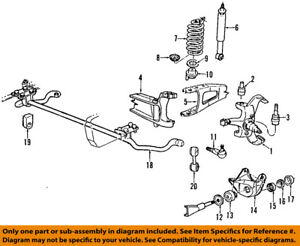
1980 to 1998 FORD F250 and F350 with DANA 50 IFS Independent Front Suspension. It's easy to spot the FORD Dana 50 IFS Twin Traction Beam front because it uses OUTSIDE Snap Ring style axle u-joints. Diagram # Part # Description: Diagram # Part # Description: 1 ***** Housing: 42 ***** Right Knuckle: 2 707239-2X: Ring and Pinion: 43 ***** Left Knuckle: 3 ***** Left …
More about "ford f350 front suspension diagram recipes" · 2012 FORD F250 FRONT AXLE PARTS DIAGRAM – DIAGRAM · 2009 FORD F-350 REPLACEMENT SUSPENSION PARTS - CARID ...
Products 1 - 30 of 2911 — Suspension parts deteriorate over time. Don't wait for total failure, restore ride and handling on your Ford F-350 with our ...
FuseAmpsCircuit ProtectedF2.115AAdjusteble PedalF2.220APower Point, Console (19N236)F2.320APower Point, C Pillar (19N236)F2.420APower Point, Instrument Panel (19N236)F2.520APower Point, Rear (19G247)F2.620ATurn Signal Relay, Trailer TowF2.730AHeadlamps, High Beam/Flash to PassF2.815AReversing LampsF2.920APower …
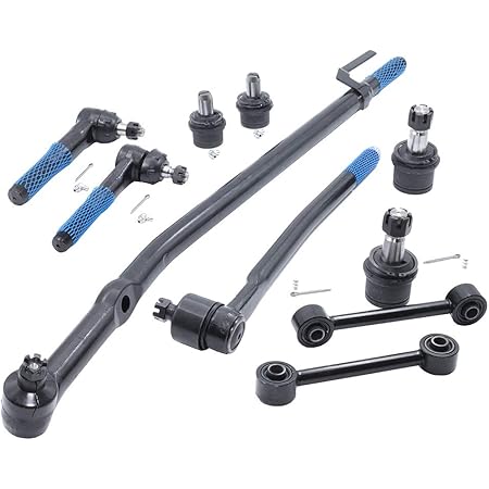
Includes all steering linkage and ball joints needed. All included parts are made by MOOG and backed by a 3 year to limited lifetime warranty. In stock to ship ...
About Hose Diagram G35 Vacuum 2007 infiniti g35 heater hose diagram Original Nissan Repair Manualswritten by Nissan specifically for the year and vehicle(s) listed. Some small changes were made to the G35 coupe for the 2005 model year, but otherwise it remained Is-fuca-z33 Isr Performance Front Upper Camber Arms Nissan Infiniti (31. 770 x 535 pixel image type. We go …
24 Mar 2014 — Ford Powerstroke 99-03 7.3L - Front Suspension Diagram - Hey folks, just smashed the front end on a 2000 F350 Dulley.
21/04/2020 · Oem 2017 ford f 250 super duty per components front parts gz 1813 f250 engine mounting diagram schematic wiring oem 2007 ford f 250 super duty front axle parts ford f 250 oem parts diagram f250 craigslist highboy 4x4 truck mud. Whats people lookup in this blog: Ford F 250 Oem Parts Diagram
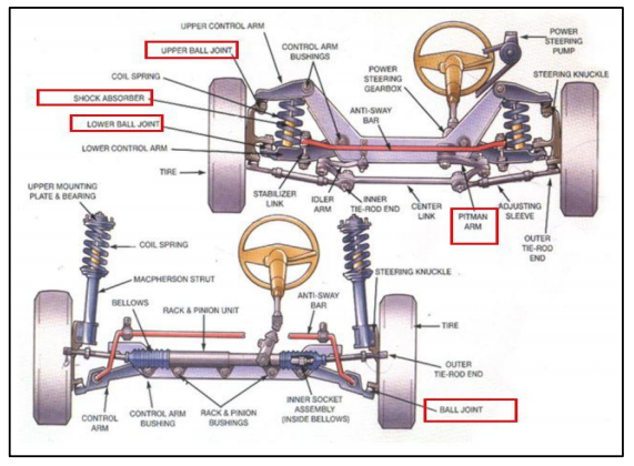
Steering and Alignment Parts · Front End Alignment Kit · Front End Steering Rebuild Kit · Front Inner Tie Rod End · Front Outer Tie Rod End · Idler Arm · Pitman Arm ...
Check integrity of each circuit. dt466 engine fuel pressure sensor location diagram auto. Help. dt466 570 ht570 engine oil pressure sensor dt466e. 3 Liter Powerstroke motors used in F250-F350+ as well as school buses and Dt466 400 Air Intake Sensor Location symptoms of a bad or failing manifold absolute pressure, cummins isl g engine electronic management system, egr …
Caster, Camber & Toe Explained CASTER. Caster is the fore or aft slope of the steering axis.The steering axis is a line drawn through the upper and lower ball joints of the knuckle. Positive caster is when the bottom of the steering axis line is in front of the tire's contact patch.
10pc complete front suspension steering kit replacement for ford excursion f-250 f-350 super duty 2wd models only inner & outer tie rod ends & upper & ...

Front suspension for 2008 ford f-350 super duty | quirkparts

Details about ford oem 05-07 f-350 super duty front suspension-shock au2z18v124ac
Moog-packagedeal304 | front end rebuild kit | 2008-2010 ford ...

Front suspension for 2008 ford f-350 super duty | quirkparts

2020 ford tremor suspension | how it works | f-250 super duty, f ...
Details about ford oem 92-97 f-350 front suspension-spacer e5tz3b244a

Ford escape, diagram, f350

Suspension components for 2017 ford f-250 super duty | tascaparts.com

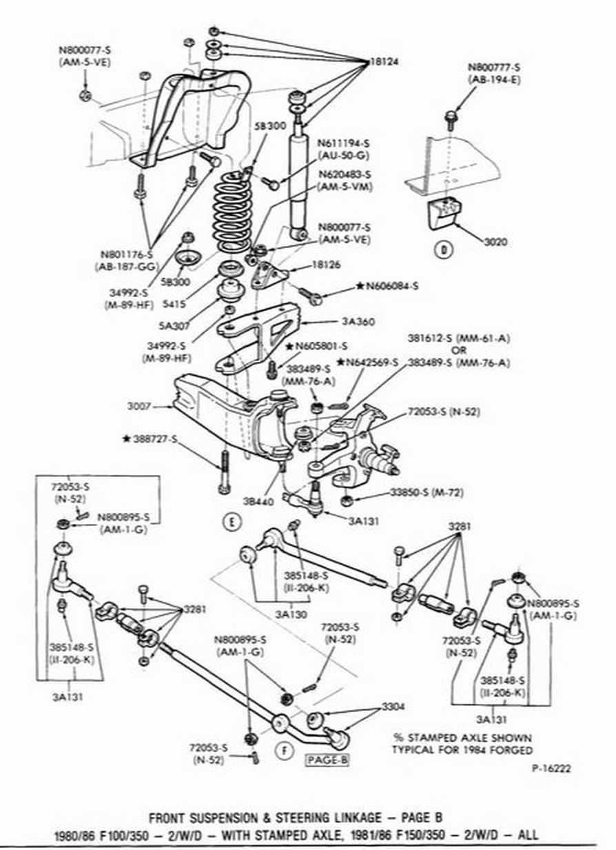
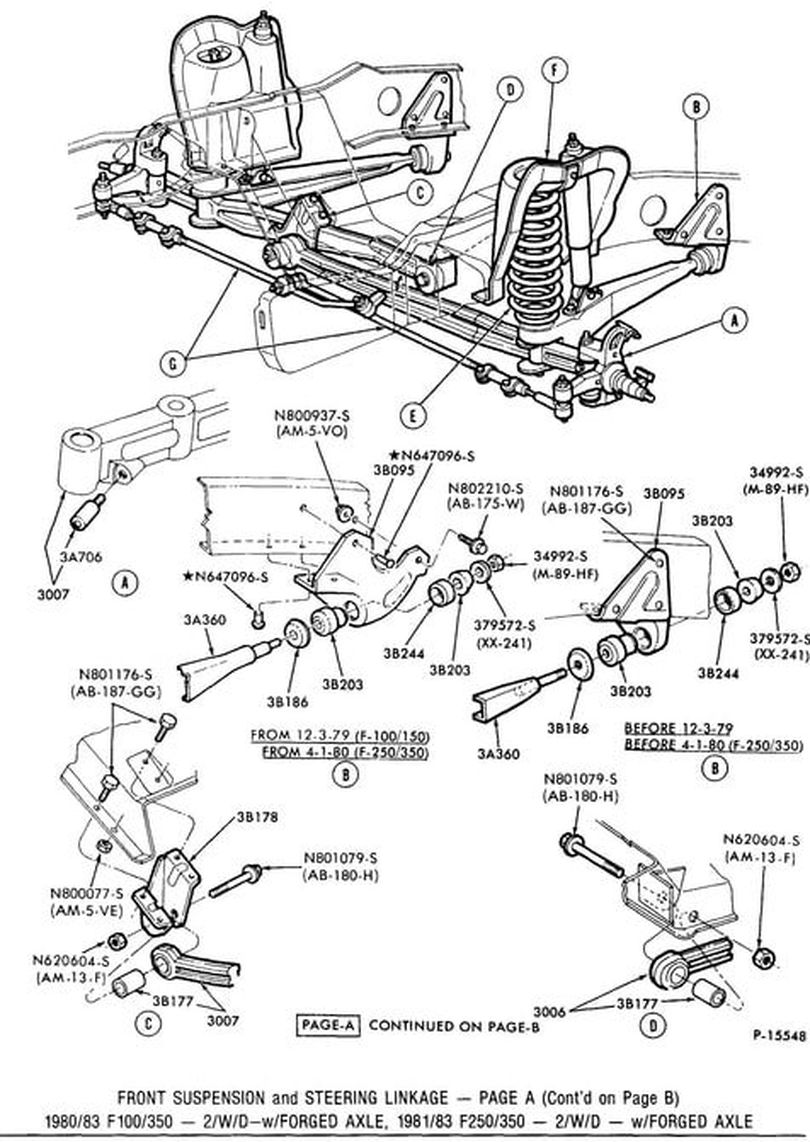
Ford truck technical drawings and schematics - section a - front ...

Does any one have schematics or diagrams for a ford f350 1993 i ...
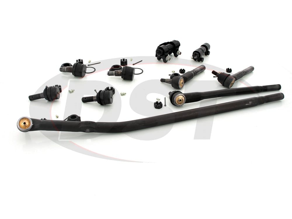
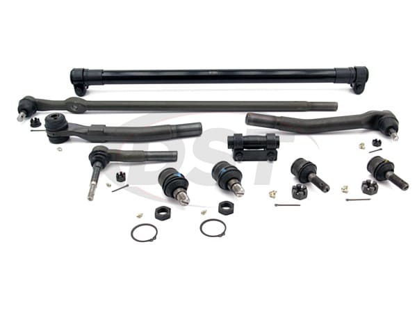
Front end steering rebuild package kit - twin i beam axle
Front suspension

Amazon.com: 12 pc front suspension kit inner & outer tie rod ends ...
Front suspension

Suspension components for 1984 ford f-350 | fairway ford parts
Front suspension for 2005 ford f-250 super duty | haag ford parts
Ford hit with 'death wobble' class action over alleged suspension ...
.jpg)
Dana 60 front differential and axle parts for ford super duty 2005 ...
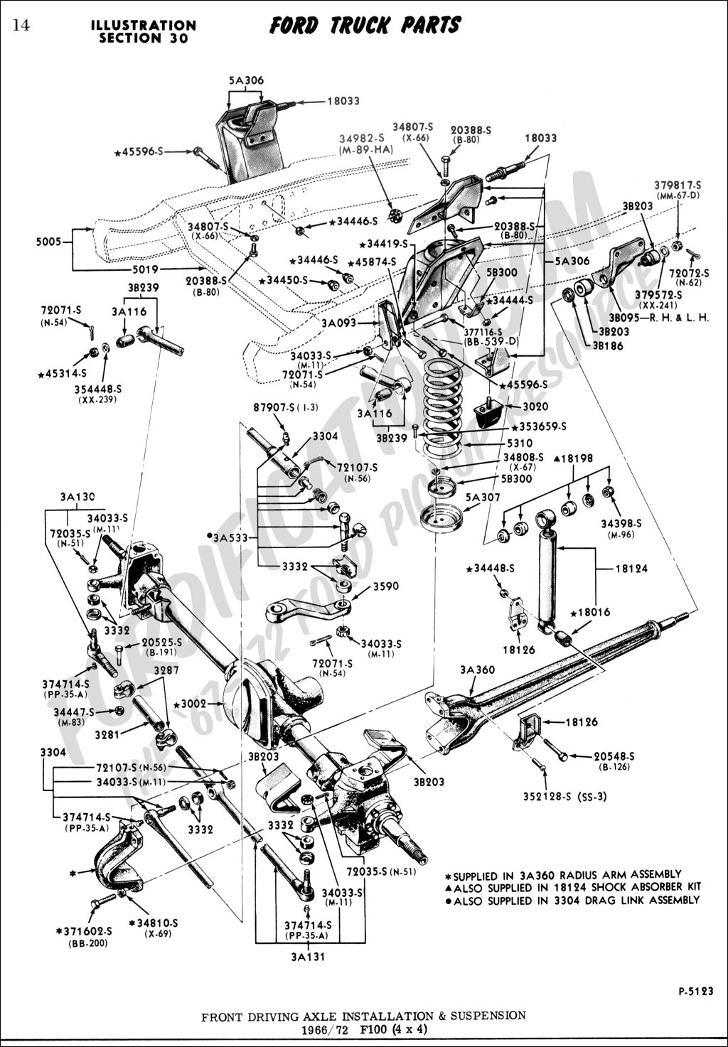
Ford truck technical drawings and schematics - section a - front ...

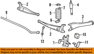
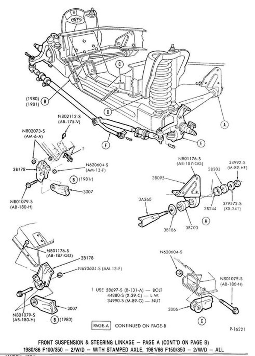
2-wheel drive coil spring front suspension
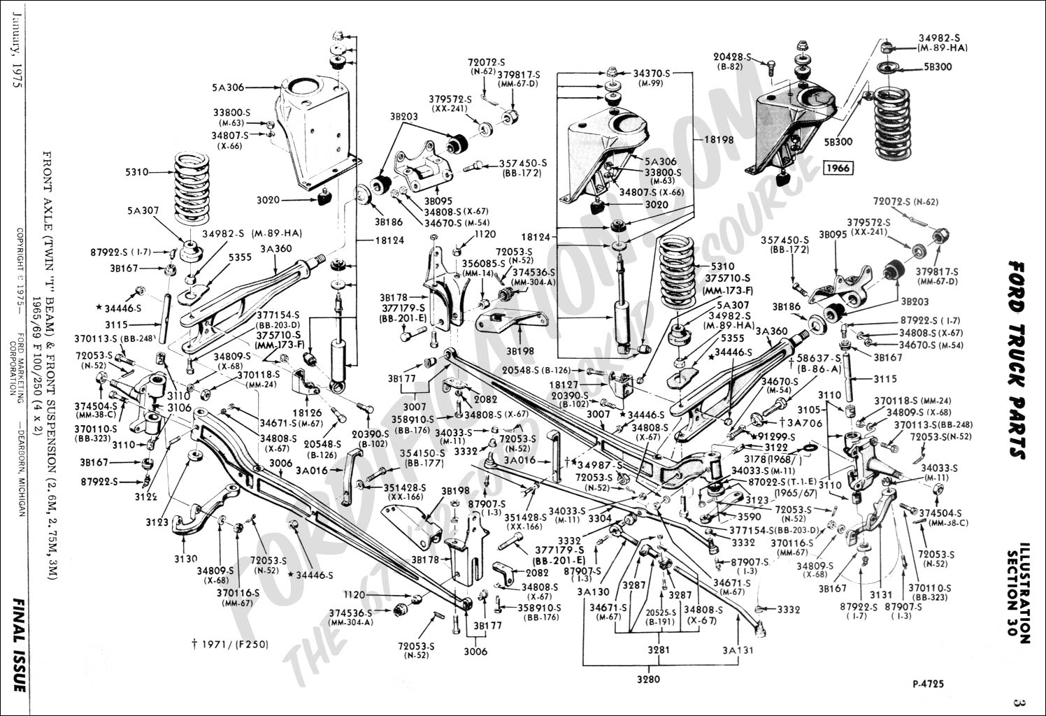
Ford truck technical drawings and schematics - section a - front ...
Steering arm, drag link & stabilizer 2011 f350 super duty

Suspension components for 1997 ford f-250 hd | oem parts
2006 f250 front end parts list - ford truck enthusiasts forums
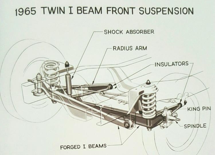
Ford twin i-beam suspension – blue oval trucks

Ford truck technical s and schematics section a front rear axle ...
Details about ford oem 99-07 f-350 super duty front suspension-shock absorber au2z18v124am

Moog_packagedeal012 | front end rebuild kit | 99-04 ford f-250 ...

Buy detroit axle - 4wd front 10 piece complete front suspension ...
Moog tie rod end and drag link parts schematic - ford truck ...
Moog tie rod end and drag link parts schematic - ford truck ...
Front suspension
Front end rebuild 2003 f350 | ford powerstroke diesel forum

Ford oem 11-16 f-350 super duty front suspension-shock absorber bc3z18124b | ebay
Front end rebuild 2003 f350 | ford powerstroke diesel forum

12+ ford truck suspension diagram - truck diagram - wiringg.net ...

Ford f350 4wd 1997 | energy suspension parts

Suspension components for 1997 ford f-350 | wade ford parts
0 Response to "40 f350 front suspension diagram"
Post a Comment