39 120 to 24 volt transformer wiring diagram
24 Volt Transformer Wiring Diagram – Trusted Wiring Diagram Online – 24 Volt Transformer Wiring Diagram. Wiring Diagram arrives with several easy to adhere to Wiring Diagram Instructions. It really is intended to aid all the typical user in building a suitable program. These instructions will likely be easy to comprehend and apply.
120V. 240V. 110V. 220V. 11.5V. 23V. 12V. 24V. 11V. 22V. PH***PG Schematic for 50, 75 and 100VA Units. High Voltage (HV). Install Supplied Links.9 pages
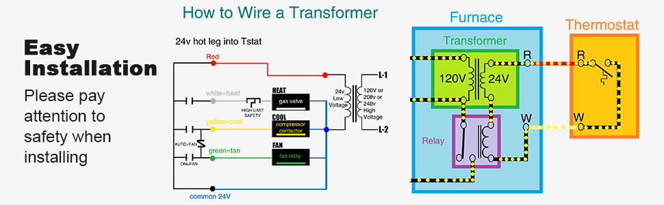
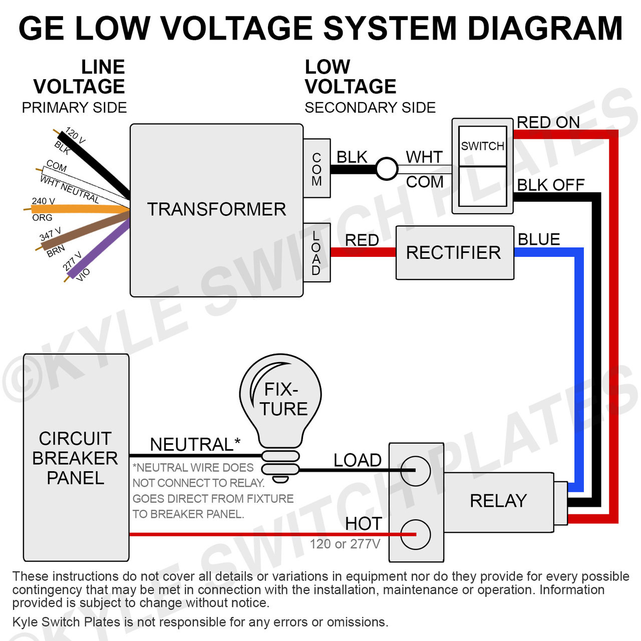
Typical wiring diagram for heat only, 3-wire, single transformer systems TRANSFORMER Heating System Fan Relay C‡ Y RC JUMPER WIRE B O For 2-wire Heat only, attach to RH and W NOTE Y RH 24 VAC 120 VAC Hot Neutral TRANSFORMER THERMOSTAT SYSTEM G W Figure 3. Typical wiring diagram for cool only, 3-wire, single transformer systems Cooling …

120 to 24 volt transformer wiring diagram
The Functional Devices RIB TR Series offers a complete line of control transformers for use in building automation and temperature control systems. The series includes transformer VA ratings from 20 VA up through 375 VA and primary voltages of 120, 208, 240, 277, and 480 VAC. Isolation transformers for 24 VAC circuits are also included. All RIB TR Series transformers are UL listed and feature ...
For 120 volt primary you would parallel the windings tying 1&3 and 2&4 together and apply 120 volts AC. For 240 volt operation the primaries go in series and you would tie 2&3 together and apply 240 volts AC to 1&4. The secondary should be as drawn. If you plan to use this you should understand it and be careful working around mains power.
Control Transformers, Primary Voltage of 120/240V, Secondary Voltage 12/24 with Power Rating of 25VA to 350VA
120 to 24 volt transformer wiring diagram.
If you are using this unit as an isolation transformer with a primary of 120 or 240 or 480 volts and the secondary of 1224 1632 or 2448 depending on the model use the wiring diagram located on the inside of the cover to the wiring compartment.
A wiring diagram and an annotated wiring guide are provided on the back. Figure 1: 826-2693, 120/208V/240V/24V Transformer Kit. 819-6508.2 pages
ACME ELECTRIC U MILWAUKEE, WI U 800.334.5214 U acmetransformer.com 125 GENERALGENERAL ELECTRICAL CONNECTION DIAGRAMSACME® TRANSFORMER™ WIRING DIAGRAMS PRIMARY: 240 Volts Delta SECONDARY: 208Y/120 Volts TAPS: 2, 5% BNFC X1 H1 X2 X3 H2 H3 X0 3 2 1 3 2 1 3 2 1 ConnectConnect Primary Primary Inter- Secondary
I am not sure why you said 2pcs of 120ah12V battries in series. He needs batteres to supply the 1500w loads for 12hours at night. Basically that is 1500w * 12 = 18000wh. dividing by 50% depth of discharge as you choose flooded, that is 18000/0.5=36000wh or divde by 0.8 if for AGM batteries, that is 18000/0.8 = 22500wh.
120V To 24V Transformer Wiring Diagram from www.swgr.com. Print the electrical wiring diagram off in addition to use highlighters to trace the signal. When you use your finger or perhaps stick to the circuit with your eyes, it’s easy to mistrace the circuit. 1 trick that I 2 to printing the same wiring picture off twice.
Edwards Signaling manufacturers a complete line of audible and visual signals for industrial and commercial applications. Products include: fire alarm control panels, flashing and steady LED and halogen beacons and lights, strobes, vibrating horns and bells, outdoor warning sirens, public address ...
Control Transformers: The ImperviTRAN™ product offering is available from 25VA through 5,000VA in any 600 volt class voltage combination. All designs meet UL, cUL, CSA or EN61558-2-2 and can be built in 105°C, 130°C, 155°C or 180°C
120 Volt to 24 Volt Transformer Wiring Diagram – wiring diagram is a simplified okay pictorial representation of an electrical circuit. It shows the components of the circuit as simplified shapes, and the talent and signal links surrounded by the devices.
120 To 24 Volt Transformer Wiring Diagram Free Download. October 2, 2019 by Wiring Diagram. Just what Wiring Diagram? The wiring diagram is a simple visual representation from the physical connections and physical layout of the electrical system or even circuit. It shows how the power wires are interconnected and will also display where ...
If you are using this unit as an isolation transformer with a primary of 120 or 240 or 480 volts and the secondary of 12/24, 16/32, or 24/48 (depending on the model) use the wiring diagram located on the inside of the cover to the wiring compartment. If you are using this unit as an auto transformer to buck (lower) or boost (raise) the voltage ...
24 VAC 120 C Hot Neutral THERMOSTAT SYSTEM G W Figure 2. Typical wiring diagram for heat only, 3-wire, single transformer systems TRANSFORMER Heating System Fan Relay Y RC JUMPER WIRE B O For 2-wire Heat only, attach to RH and W NOTE Y RH 24 VAC 120 VAC Hot Neutral TRANSFORMER THERMOSTAT SYSTEM G W Figure 3. Typical wiring diagram for
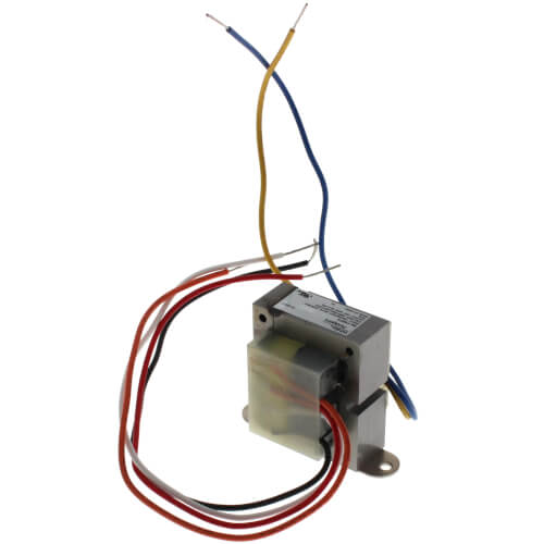
August 14, 2007 - Each wire is a lead to the transformer primary. The wires are color coded to the different voltages (neutral, 120, 208, 240). I could guess on the color code, but I'm not sure. The screw terminals are the 24V secondary.
28 amp relay (replaces all relays, requires large transformer)
• Industrial Control • Encapsulated 600 Volt Class • Ventilated 600 Volt Class • DOE 2016 Efficiency Compliant . 2 Federal Pacific History In 1987, the Electro-Mechanical Corporation acquired the dry-type transformer division of Federal Pacific Electric in Des Plaines, Illinois. It was moved to Bristol, Virginia and the name was changed to Federal Pacific (FP). A new …

50 luxury 90340 relay wiring diagram | thermostat wiring ...
120 Volts Switching Relay Wiring Diagrams ZONE 1 ZONE 2 ZONE 3 FUSE 1 AMP Z ONE 1 ZONE 2 ZONE 3 POWER ZONE 1 ZONE 2 N P ZC H X1 X2 R COM / 24 VAC Switching Relay SR-502/503 Water Heater Circulator Switching Relay R8845U and SR 501 ... Transformer Thermostat Burner TV T Z C1 C2 L1 L2 B1 B2 120 Volt Boiler Circulator L8124E R H

Pin on quick saves
Free delivery on millions of items with Prime. Low prices across earth's biggest selection of books, music, DVDs, electronics, computers, software, apparel & accessories, shoes, jewelry, tools & hardware, housewares, furniture, sporting goods, beauty & personal care, groceries & just about anything else.

24 volt transformer mr 50354
Step Up Down And Isolation Transformers Worksheet Ac Electric Circuits. 3000va Control Transformer 440 460 480v To 120 24v Ato Com. Lanmu 8541553743 Lnamu 24 Volt Transformer 24v C Wire Adapter Power Supply Compatible With Nest Honeywell Ecobee Emerson Sensi. Wiring Of Control Power Transformer For Motor Circuits Eep.

How can i use a separate transformer to provide a c wire to ...
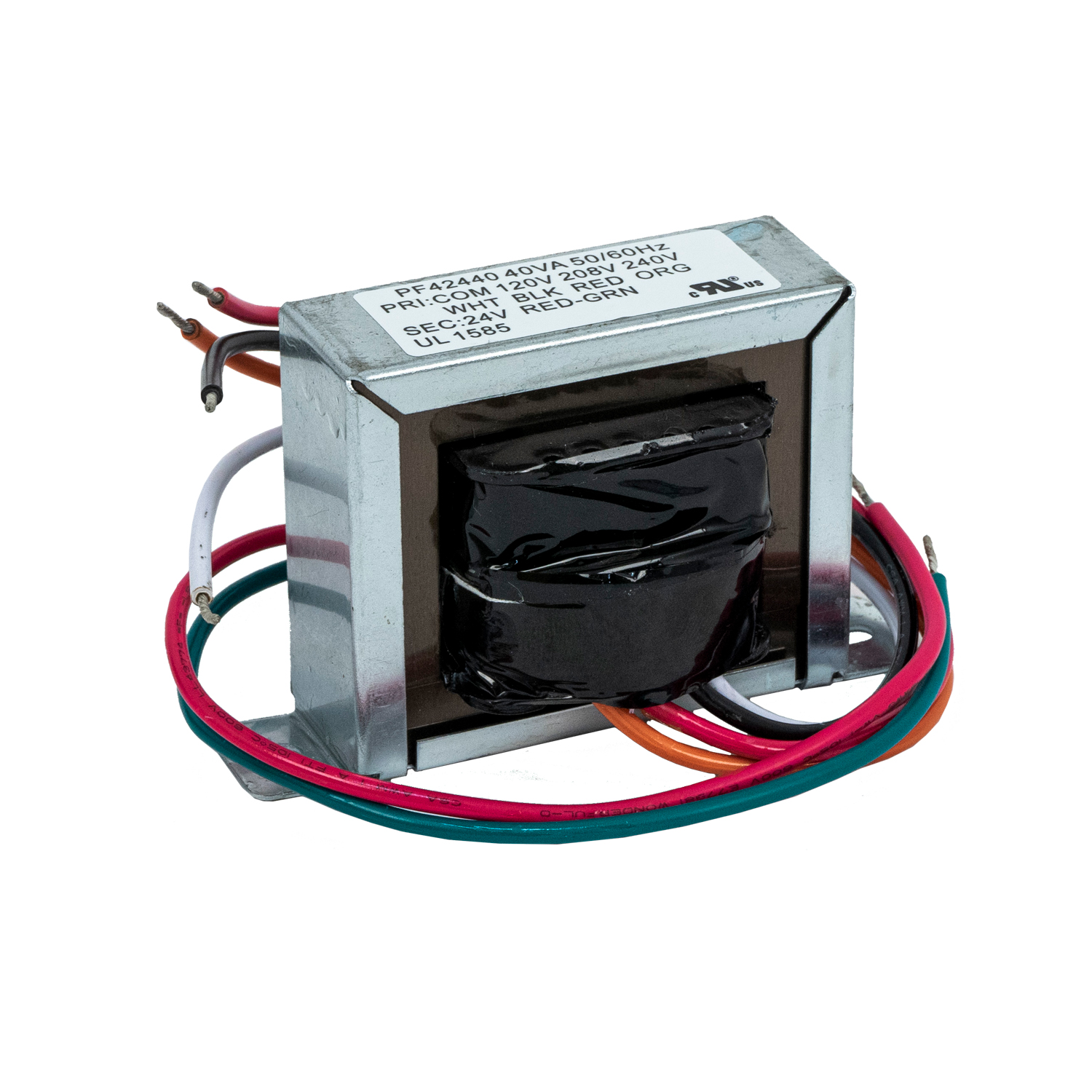
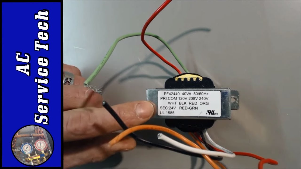
Packard PF42440 transformer 120-208-240V 40VA 24V 120 volt instructions: Connect white and black wires to 120V input. Connect red and green wires to 24V output. 208 volt instructions: Connect white and red wires to 208V input. Connect red and green wires to 24V output. 240 volt instructions: Connect white and orange wires to 240V input.

How to wire a transformer in series or parallel (with animation) | basic electronics
May 22, 2020 - 50 Luxury 90340 Relay Wiring Diagram- A manage relay is used in the automotive industry to restrict and alter the flow of electricity to va...
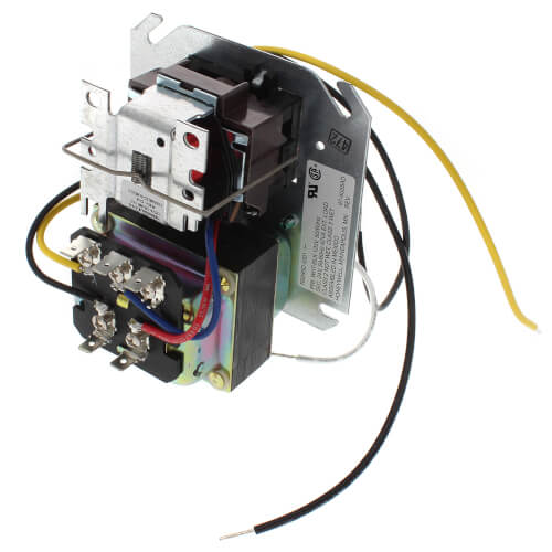
Transformer-relay, 120/24v
A 24 vac volt alternating current transformer is a step down type of transformer. General electrical connection diagramsacme transformer wiring diagrams. So for 480 v input the two 240v primaries are in series and to get the 120 volt output the two secondaries are in parallelone of the usa 3 phase voltages is 480v you can run a single phase ...

Control transformer 40va, primary 120, 208, 240v secondary 24v, hvac furnace multi tap
Understanding how Transformers work including step down transformers and autotransformers (Variacs), how they are connected, and different types with a focus on their use in hot wire foam cutter power supplies and other heating applications.

How to wire 3-wire motorized ball valve
iCreatin 24V 36Watt Superior Quality Waterproof LED Power Supply Driver Transformer 120 to 24 Volt DC for LED strip and more. (36 Watts) 4.2 out of 5 stars. 102. $13.98. $13. . 98. Get it as soon as Thu, Nov 11. FREE Shipping on orders over $25 shipped by Amazon.
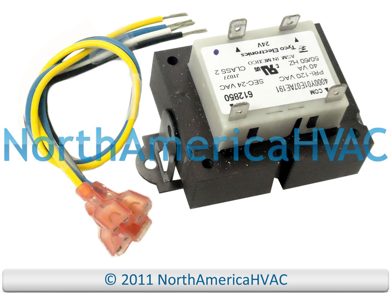
Icp heil tempstar transformer 110 120 24 volt 612850
Great fun comes with great knowledge of the ocean. Bay of Life combines knowledge, science and sport in the teaching methodologies for a wholesome and proper introduction to the world of ocean sports and surfing in Chennai · Learn surfing at Bay of Life, Chennai’s first accredited surf school.

Details about intertherm nordyne miller furnace transformer 24v / 120 208 240v + fuse + instr.
Honeywell 24 Volt Transformer Wiring Diagram – wiring diagram is a simplified conventional pictorial representation of an electrical circuit. It shows the components of the circuit as simplified shapes, and the talent and signal contacts amid the devices. A wiring diagram usually gives opinion just about the relative point of view and treaty ...

Amazon.com: mars - motors & armatures 50354 40va 120/208/240v ...
220 Volt Wiring Diagram; Wiring 220 Volt Electrical Outlet . Home electrical wiring includes 110 volt outlets and 220 volt outlets and receptacles which are common place in every home. See how electrical outlets for the home are wired. The following may also be helpful for you: Electrical Wiring Video #2 Home Electrical Wiring Videos about this Topic and More Check out my …
Foot mount transformer primary 120/208/240v secondary 24 ...
Feb 20, 2019 - 24 volt thermostat transformer wiring diagram, 24 volt transformer wiring diagram, 480 to 24 volt transformer wiring diagram, edwards 24 volt transformer wiring diagram, volovets.info
Which hvac 24v transformer can you use for replacement on almost every unit! transformers
24 Vo lt 120V Hot To 120V Power This configuration allows the humidifier to run whenever there is a call for heat. Make sure the "HUM" terminal is 24 volts and not 120 volts. If the terminal is 120 volts, a 24 volt transformer will have to be installed. (Refer to your furnace's manual for voltage.) Diagram #3 Aprilaire Automatic ...

Transformer 24v output
How to wire a multi tap transformer functional devices inc basics information guide control transformers power voltage stepdown converters 5s1f dry 5kva 240x480v 120 240v schneider electric usa feeders 1 phase 2 ecn electrical forums and encapsulated 600v class small cte in 240 110v wiring of for motor circuits eep configure vertex p n 0060 102 1021 230… Read More »
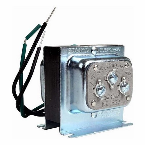
592 - 8/16/24v ac transformer
120V. 110V. 11.5V. 12V. 11V. 21 3. 5 6. 4. 230V. 240V. 220V. 3 2 1. 456. 23V. 24V. 22V. HPS IMPERATOR® Series - Wiring Schematic Drawings continued.9 pages

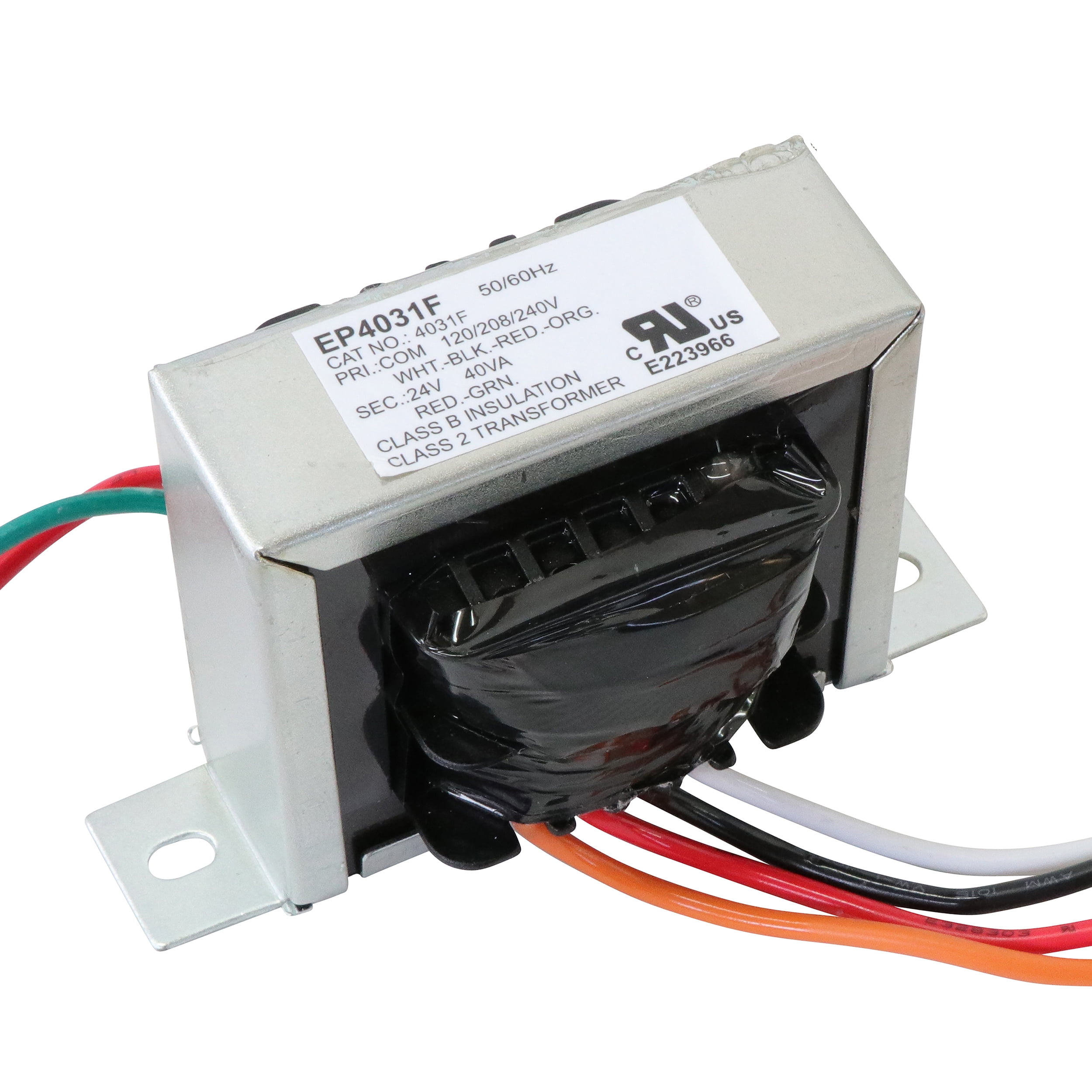
Details about universal 24 volt transformer 120/208/240 40 va 60hz 40310f hvac- 6 hour ship!
August 5, 2013 - If this is the case then the connections have to be in parallel for 120V input and 12V output, or in series for 240V input and 24V output. They also have to be connected in proper phase. Do you have a connection diagram with the new transformer, and do you know what input and output voltages you ...
Transformer, 40va, 60 hz, 120/208/240v primary, 24v secondary, foot mount
24 Volt Transformer Wiring Diagram – 120 volt to 24 volt ac transformer wiring diagram, 208 to 24 volt transformer wiring diagram, 24 volt furnace transformer wiring diagram, Every electric structure is composed of various distinct parts. Each part should be set and connected with other parts in specific manner. Otherwise, the arrangement will not work as it should be.
503 series foot mount transformer 120/208/240 to 24v 40va
The C-terminal is the 24 volt common (as opposed to hot). This terminal is necessary to power thermostat as the thermostat needs a source of power to operate. This terminal is kind of like the neutral side of a 120-volt circuit. A basic circuit needs a source, a path, and a load. In this case, the source is the transformer, the load is the ...

4-1611453-7 - productsunlimited - te connectivity ...
120VAC Input. Marcus transformers only. Used for Nema23 motors and drivers only. +. (white). (black).1 page
Control transformer 40va, primary 120, 208, 240v secondary ...
Results 1 - 48 of 1000+ — 24V LED Power Supply - Lustaled Waterproof IP67 15W 24 Volt DC Transformer 120V AC to 24V DC Constant Voltage Outdoor LED Driver ...

Control circuits for hvac systems quality hvac tips 101
A 24 VAC (volt alternating current) transformer is a step-down type of transformer. The device typically converts 120 VAC to a lower voltage for use in push buttons. The most common application for a 24 VAC transformer is to activate a doorbell chime. The lower voltage is sent to the push button to engage the chime mechanism.

120v/24v transformer for brooders | hog slat
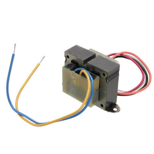
November 24, 2013 - It's just a transformer. Measure the line voltage that you have to find out if it is 120 volts, 208 volts or 240 volts. If you have 240 volts, cap white and red individually and connect one of your line voltage wire to black and the other to orange. If you have 120 volts that you wish to step ...
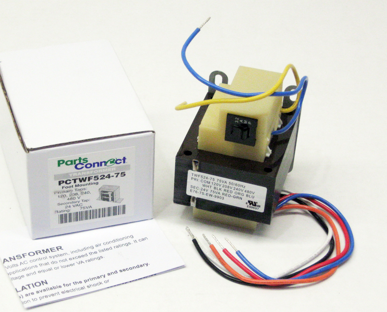
75va transformer primary 120v 208v 240v 480v volt 24v secondary hvac furnace multi tap
120v 24v transformer for brooders hog slat integration kit relay with built in honeywell home 24 volt at72d the 592 edwards 8 16 ac hvac wiring confusion doityourself com community forums low voltage transformers i need from m2170 multi tap help me diagram and it up all about circuits rewiring adding vac external place of c wire sensi… Read More »
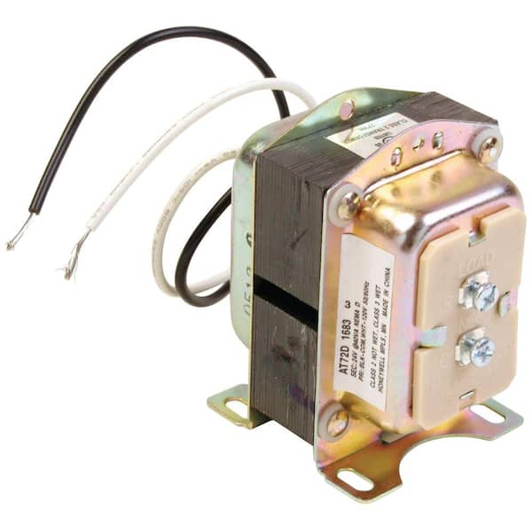
Honeywell home 24-volt transformer-at72d - the home depot
distribution transformers single phase hvdt wiring data three phase hvdt wiring data ps primary* secondary wiring ps primary* secondary wiring code (volts) (volts) diagram code (volts) (volts) diagram ... 24 2400/4160y 480 2 24 4160 480y/277 3 25 4160 600 4 31 4160 120/240 1 31 4800 208y/120 3

Protactor universal furnace transformer 115-208-240 volt primary 24 volt secondary 40 va
Do-it-yourself process of adding a 24 VAC external transformer in place of C wire for heat-only system that is connected to your Sensi thermostat. Click to learn more.
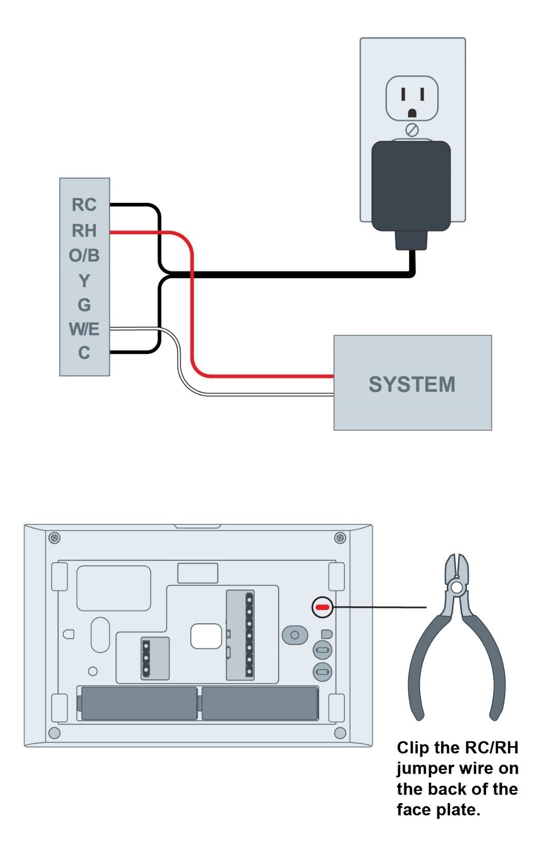
Adding 24 vac external transformer in place of c wire | sensi us
12.07.2017 · September (120) August (123) July (123) June (106) ... 24 volt trolling motor battery wiring diagram; 240 volt single phase wiring diagram; 240v single phase wiring diagram ; 240v single pole circuit breaker wiring diagram; 240v single pole thermostat wiring diagram; 24v 8 pin relay wiring diagram; 24v trailer socket wiring diagram; 277 volt single phase …
Endurance pro control transformer 40va, primary 120, 208, 240v secondary 24v, hvac furnace multi tap, jard 4031f, packard 42440
Buck-Boost Transformer Installation Sheet Revised on April, 2011 by T.E. If you are using this unit as an isolation transformer with a primary of 120 or 240 or 480 volts and the secondary of 12/24, 16/32, or 24/48 (depending on the model) use the wiring diagram located on the inside of the cover to the wiring compartment.
Ge lighting low voltage transformer 115v 277v
Controllers can be ordered for 12 volt AC\DC, 24 volts, 120 volts and 240 volt AC operation. Shipped standard 120 volts to the US and Canada, 240 volts the UK, Australia, New Zealand and other countries, all at the same low price. No need to travel to a hardware store for power cords, wire and mounting hardware, everything needed to install your controller is shipped complete …

Transformer with wire leads and quick connect universal 24 vac 40 va 120/208/240 volt 60 hz primary tp-40va
120 Volt To 24 Volt Ac Transformer Wiring Diagram. Author: Ryan Published Date: December 4, 2021 Comments: Leave a Comment on 120 Volt To 24 Volt Ac Transformer Wiring Diagram. Pin On Electronice . 0 24 Volt 2 Amp Bench Top Power Supply Make Power Supply Analog Circuits Power .

Buck boost transformer
120 240 Transformer Wiring Diagram. 0 075 kva transformer primary 240 x 480 secondary 120 federal pacific se2n f figure 4 17 single phase connected to give volt three wire service connections the electricity forum 5s1f dry 5kva 240x480v 240v schneider electric usa how a multi tap functional devices inc power distribution configurations with 3ph ...
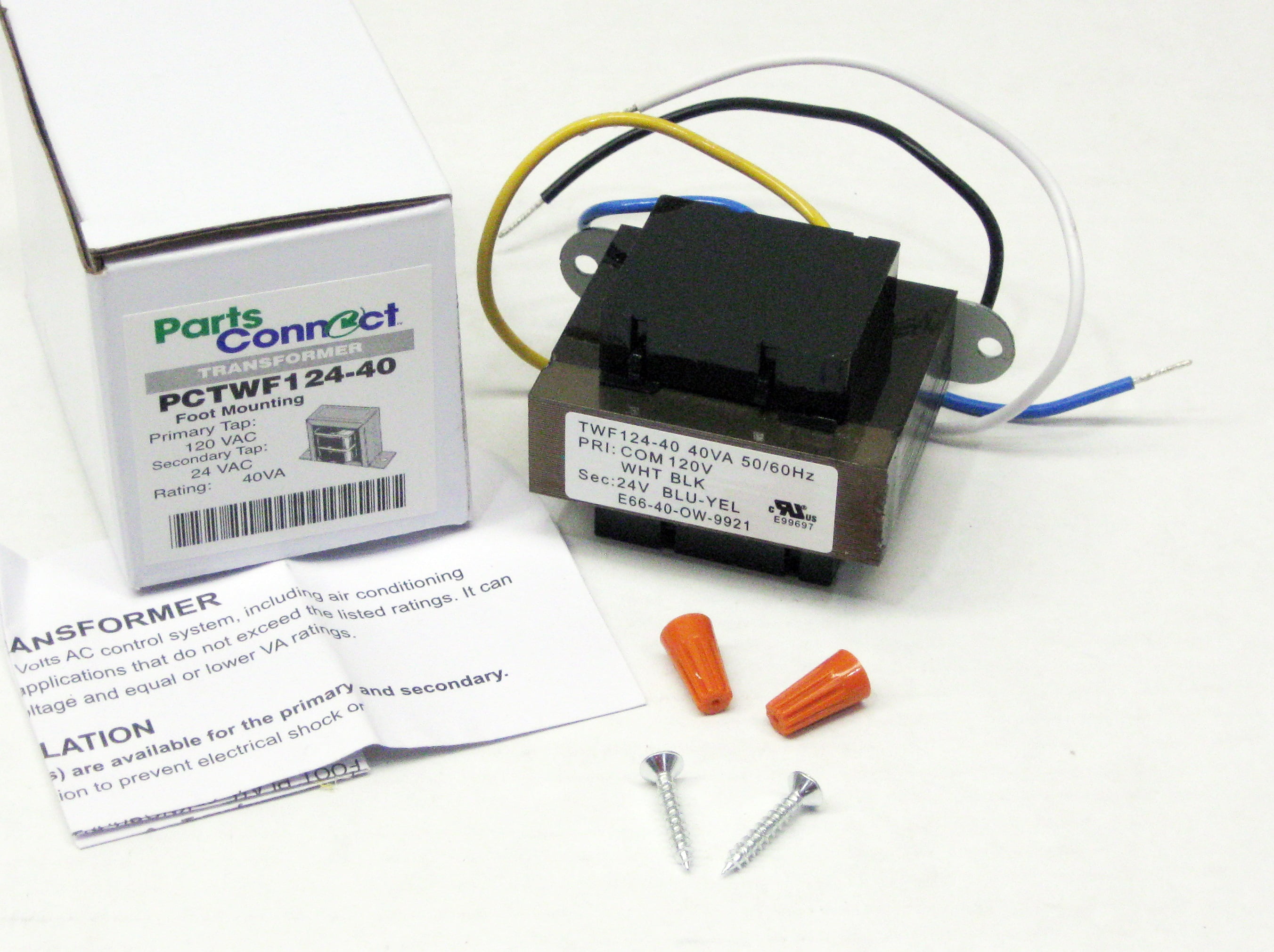
40va transformer primary 120v volt 24v secondary hvac furnace foot mount
Secondary voltage The secondary voltage for KMC transformers is 24 volts AC ... transformer and wiring from current that exceeds the capacity of the circuit.8 pages

Control circuits for hvac systems quality hvac tips 101
24 Volt Transformer Wiring Diagram - Trusted Wiring Diagram Online - 24 Volt Transformer Wiring Diagram. Wiring Diagram arrives with several easy to adhere to Wiring Diagram Instructions. It really is intended to aid all the typical user in building a suitable program. These instructions will likely be easy to comprehend and apply.

120v/24v transformer for brooders
24V Transformer 120 To 24 Volt Transformer Wiring Diagram. Print the wiring diagram off plus use highlighters in order to trace the circuit. When you make use of your finger or stick to the circuit with your eyes, it may be easy to mistrace the circuit. One trick that We use is to print exactly the same wiring plan off twice.
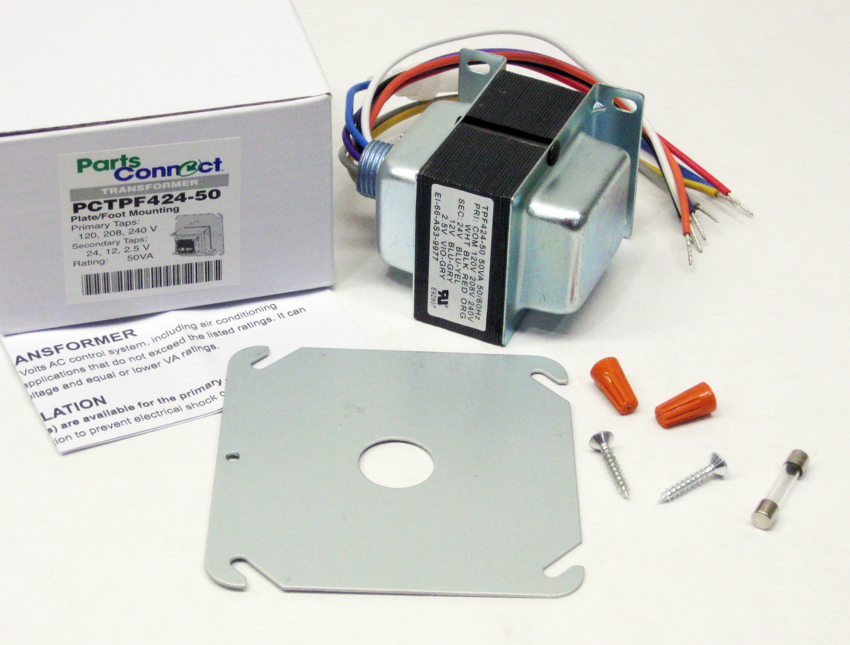
50va transformer primary 120v 208v 240v volt 24v, 12v, 2.5v secondary hvac furnace multi tap
120 to 24 volt transformer wiring diagram. A 10 kva transformer volt secondary is to service an 8 kva. The color of the wires may be different. A 120 volts connected to the black red wires provides only 12 volts at the secondary. A 24 vac volt alternating current transformer is a step down type of transformer.
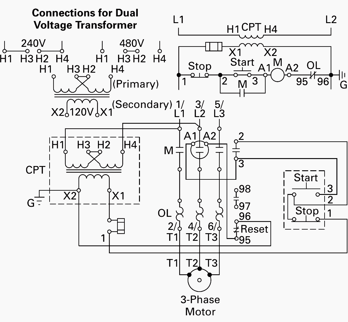
Wiring of control power transformer for motor control ...
It claims to control a 240 volt heater, but no device with only 3 wires can switch two 120 volt legs. You need a minimum of 4 wires (corresponding with line and load ends for both legs) in order to do that. So this device is clearly not a DPDT or a DPST relay. I am pretty good with electrical wiring, but for the life of me could not figure this device out. A friend of mine that is a master ...

40va transformer primary 120, 208, 240v volt 24v secondary hvac furnace multi tap
04.06.2019 · 06.04.2019 06.04.2019 2 Comments on 480 To 120/240 Transformer Wiring. a volt primary transformer with a volt secondary is operated at volts, regardless of whether the source is three phase 3-wire or three phase 4-wire. .. example: A 10 kVA transformer, / volt secondary is to service an 8 kVA . Single Phase Transformer Primary and Secondary wiring. Product …

Thermostat heat and cool 2 transformers | thermostat wiring ...
2. Check this wiring diagram against the wiring diagram supplied with the transformer. The color of the wires may be different. 3. The general rule is that the more winding that is connected on the primary, the lower the secondary voltage. Examples: a) 120 volts connected to the Black & Red wires provides only 12 volts at the secondary.
0 Response to "39 120 to 24 volt transformer wiring diagram"
Post a Comment