38 ttt diagram example problems
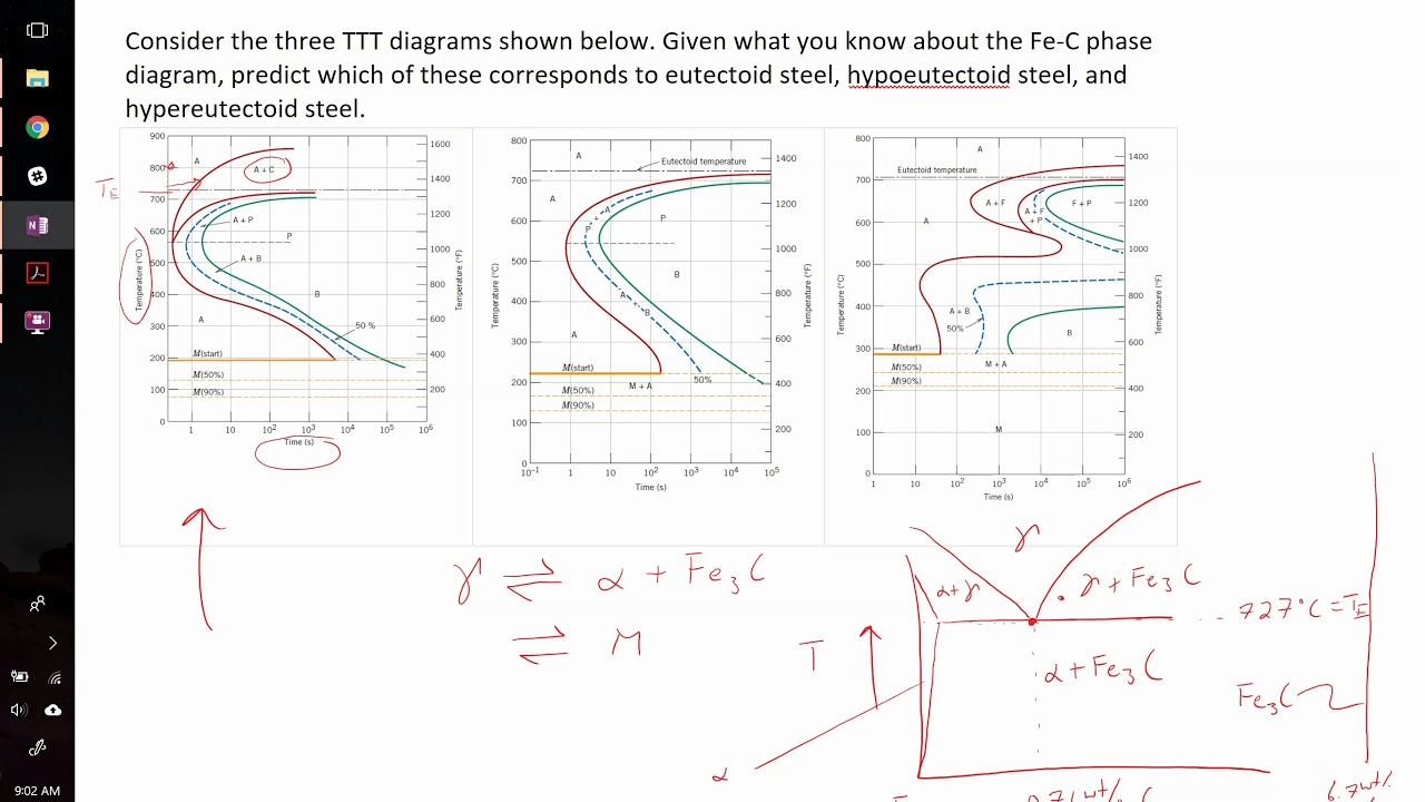
Example problem and solution showing how to match TTT diagram to eutectoid, hypoeutectoid, and hypereutectoid steel compositions. Answer (1 of 4): Hello everyone. Thank you everyone.
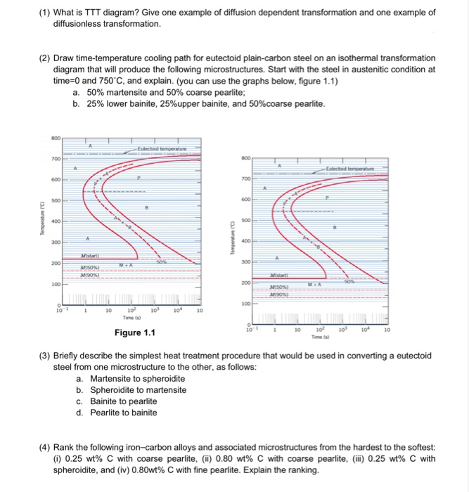
Examples on how to use TTT Diagrams

Ttt diagram example problems
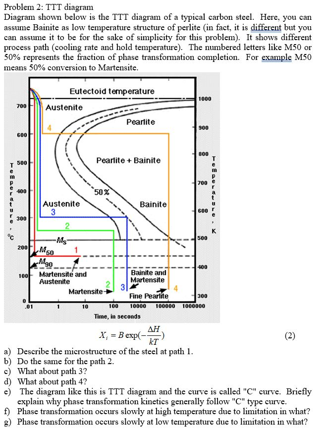
Time-Temperature-Transformation diagram is a method in material science for understanding the transformation of alloy steel. Here this quiz is specially designed for science students of this field. Let's test your level of knowledge on such a topic. Questions and Answers. 1. Transcribed image text: Time (s) Example 3 :-(home work) Samples of Eutectoid steel heated to austenite phase at (850 C) for (1 hr.),then cooling as the (TTT diagram ) as below find the final structure for each sample 1- rapid cooling to room temperature 2- rapid cooling to (690 C) and hold to 2 hr.). then, rapid cooling to room temperature 3- rapid cooling to (610 C) and hold to 3 min.). then ... time! TTT and CCT diagrams summarize the percent completion of a given phase transformation and are similar to phase diagrams except that time is included. TTT and CCT diagrams generally contain 3 distinct lines, which represent: Nucleation Line - Beginning of the Phase Transformation Process. 50% Completion of the Phase Transformation.
Ttt diagram example problems. there is no TTT diagram, the program Thermo-Calc is used with the desired chemistry to calculate the thermodynamic temperatures (for example the austenite-ferrite transition A. 3, the eutectoid A. 1, the martensite start and finish, M. s . and M. f, temperatures) along with a "similar" TTT diagram to estimate the transformation data. I don't have the CCT / TTT diagrams either but, I can tell you how I do it. I quench into oil. I warm the oil up before I use it, about as warm as a HOT bath. It is important with this steel to give it a fair soak once it gets to temperature, 5 to 10 minutes if I recall correctly. transformation (TTT) diagrams. TTT diagrams can be calculated from the chemical composition of the material. With this methods the numerical prediction often result in deviations to reality. A newly developed optimization method can improve the accuracy of phase content and hardness prediction after quenching by optimizing the TTT diagram Determination of TTT diagram for eutectoid steel Davenport and Bain were the first to develop the TTT diagram of eutectoid steel. They determined pearlite and bainite portions whereas Cohen later modified and included M S and M F temperatures for martensite. There are number of methods used to determine TTT diagrams. These are salt bath (Figs. 1-
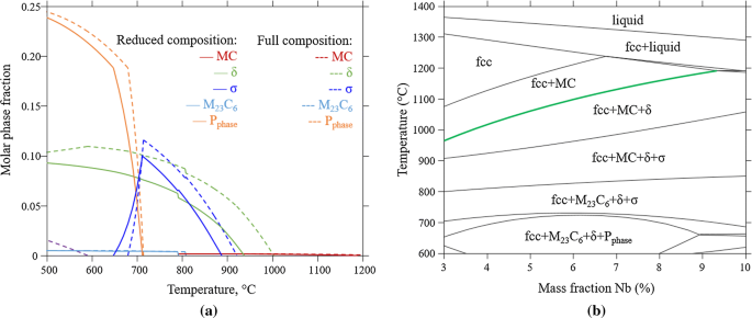
TTT diagram helps to fix the time and temperature of holding. The speed of motion of the wire through the bath should be such that it remains in bath for a time slightly greater than the time of completion of pearlitic transformation to avoid any chance of transformation of untransformed austenite to bainite, or martensite later. A more problematic situation is the decomposition of a high temperature intermetallic phase. An example is the eutectoid decomposition of Nb 3 Si in the Nb-Si binary system. The Nb-rich part of the Nb-Si phase diagram [38] and a TTT diagram [39] of a Nb-19 at.%Si alloy are shown in Fig. 2.17 (a) and (b). Even though the temperature is very high (equilibrium eutectoid temperature for ... is the TTT diagram, so called, because it represents the time taken at any given temperature for a given fraction of the transformation to get completed. The typical TTT diagram is a C shaped curve. In this case, we have used it to represent, at any given temperature, the time required for 1% transformation to complete. Use of IT diagrams: Examples Using the isothermal transformation diagram for a 1.13wt%C steel alloy determine the final microstructure (in terms of just the microconstituents present) of a small specimen that has been subjected to the following time-temperature treatments. In each case assume that the specimen begins at 920oC, and that
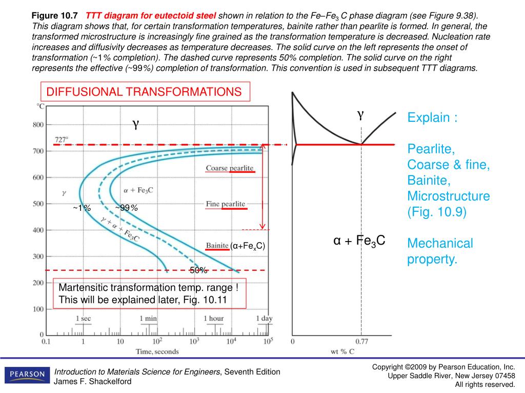
TTT & CCT Diagram Part 2 Lect-6 Dr.ABBAS KHAMMAS 2013 . Example . Austenite-to-Pearlite Isothermal Transformation Eutectoid composition, Co = 0.76 wt% C Begin at T > 7270C Rapidly cool to It takes time! Hold T (6250C) constant (isothermal treatment) T(OC) 700 • The isothermal decomposition of austenite. The TTT (time-temperature transformation) diagram. Formation pearlite and bainite. • Decomposition of austenite on continuous cooling (CCT diagram). Formation of martensite and the martensite lines. The structure of martensite. • Annealing, quench hardening, and austempering. The microstructure of iron-based alloys is very complicated, being influenced by composition, homogeneity, processing and section size. Microstructures in coarse-grained steels are much easier to observe than in fine-grained steels. Of course, steels are normally made with a fine grain size for best mechanical properties. In general, it is easiest to identify heat-treated structures after ... The diagram on the lower left shows this, it is directly taken from the figure above the TTT diagram and usually not included. If we repeat the experiment at a temperature around 480 o C (900 o F), we hit the 1 % transformation line after about a tenth of a second, and the transformation is finished after about 100 seconds.
Contents 1 301 Problems 1.1 Course Organization 1) Send an email to Prof. Shull (k-shull@northwestern.edu) and Alane (Alane.lim@k-shull@northwestern.eduu.northwestern.edu) with the following information: 1.Any background about yourself that you want to share. 2.What you have enjoyed most and have found the most frustrating about your major.

Example of CCT diagram for high-C alloy steel. After heating to 1,250℃, test piece was continuously cooled at the cooling rate of 0.1-50℃/s, transformation point was detected, and the type of transformation was determined by microstructure observation and hardness measurement after cooling.

The TTT diagram of steel is considered an important transformation diagram for non-equilibrium transformation.There are various non-equilibrium products like Martensite, Bainite which can not be formed by continuous cooling and so can not be explained with phase transformation diagram explained in Martensitic transformation post and Widmanstatten transformation post.
Time-Temperature-Transformation (TTT) diagram or S-curve refers to only one steel of a particular composition at a time, which applies to all carbon steels.This diagram is also called as C-curve isothermal (decomposition of austenite) diagram and Bain's curve.The effect of time-temperature on the microstructure changes of steel can be shown by the TTT diagram.
The use of time temperature transformation (TTT) diagrams is the focal point of this quiz and worksheet combo. The quiz will ask you about another name for a TTT diagram, along with a question ...

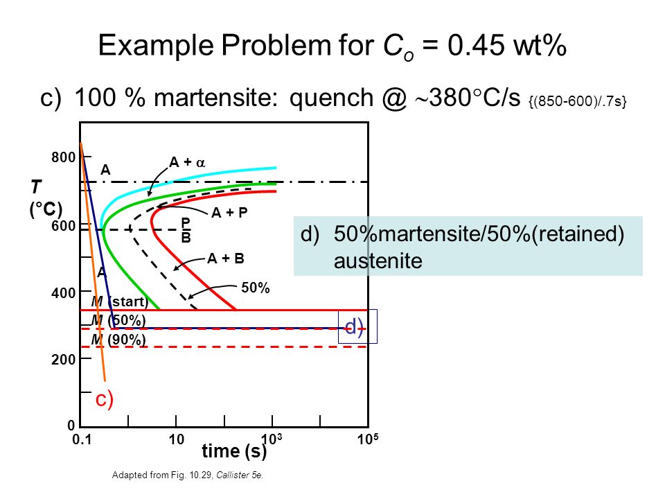
Question: TTT diagram for an iron-carbon alloy of eutectoid composition. 800 Example: Eutectoid temperature 1400 700 1200 600 1000 500 800 Temperature (0) On the isothermal transformation diagram for a 0.45 wt% C, Fe-C alloy, sketch and label the time-temperature paths to produce the following microstructures: a. 50% fine pearlite and 50% ...
On a phase diagram the intersection of the eutectic temperature and the eutectic composition gives the eutectic point. Not all binary alloys have a eutectic point, for example, the gold-silver system does not have eutectic point. The eutectic transformation is usually defined as: This type of transformation is an invariant reaction, because it ...

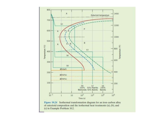
Example (1) :-Eutectoid steel cooled from austenite phase at 800 C ,then cooled as (TTT diagram ) as below , find the final structure if cooling path as following : 1- rapid cooling to (350 C) and hold to( 104 sec) , then rapid cooling to room temperature .
ADVERTISEMENTS: In this article we will discuss about:- 1. Introduction to TTT Diagrams 2. Effect of Alloying Elements on TTT Curve 3. Limitations. Introduction to TTT Diagrams: Solid state transformations, which are very important in steels, are known to be dependent on time at a particular temperature, as shown in figure. Isothermal transformation diagram, also […]
Time Temperature Transformation (TTT) Diagram: Unit 5 Martensite, 100% Example 2: Iron-carbon alloy with eutectoid composition. Specify the nature of the final microstructure (% bainite, martensite, pearlite etc) for the alloy that is subjected to the following time-temperature treatments: Alloy begins at 760˚C and has
To take one example, the effect of increasing molybdenum, Figure 1. shows the TTT diagrams for a 0.4 %C 0.2% Mo steel and steel with 0.3 %C 2 % Mo, Figure 2. The 0.2% Mo steel begins to transform in about one second at 550°C, but on increasing the molybdenum to 2% the whole C-curve is raised and the reaction substantially slowed so that the ...
time! TTT and CCT diagrams summarize the percent completion of a given phase transformation and are similar to phase diagrams except that time is included. TTT and CCT diagrams generally contain 3 distinct lines, which represent: Nucleation Line - Beginning of the Phase Transformation Process. 50% Completion of the Phase Transformation.

Transcribed image text: Time (s) Example 3 :-(home work) Samples of Eutectoid steel heated to austenite phase at (850 C) for (1 hr.),then cooling as the (TTT diagram ) as below find the final structure for each sample 1- rapid cooling to room temperature 2- rapid cooling to (690 C) and hold to 2 hr.). then, rapid cooling to room temperature 3- rapid cooling to (610 C) and hold to 3 min.). then ...
Time-Temperature-Transformation diagram is a method in material science for understanding the transformation of alloy steel. Here this quiz is specially designed for science students of this field. Let's test your level of knowledge on such a topic. Questions and Answers. 1.


0 Response to "38 ttt diagram example problems"
Post a Comment