41 consider the circuit diagram depicted in the figure
Note that all variables may not be required. α, β, θ, a, d, g, h, I 1, I 2, j, k, m, P, S, t Problem 2: Consider the circuit diagram depicted in the figure. Part (a) What equation do you get when you apply the loop rule to the loop abcdefgha, in terms of the variables in the figure? resistance in the circuit is therefore R total R r 1 r 2 where the problem tells from PHYS 002 at Howard University
(10%) Problem 1: Consider the circuit diagram depicted in the figure. <1.592 0.50 45 V A 50% Part (a) What equation do you get when you apply the loop rule to the loop abcdefgha, in terms of the variables in the figure? > A 50% Part (b) If the current through the top branch is 12 = 0.83 A, what is the current

Consider the circuit diagram depicted in the figure
Consider the circuit diagram depicted in the figure. Now apply the loop rule to loop 1 the larger loop spanning the entire circuit. Assume that v 128 v r1 r2 r3 r4 r5 200 ω. B if the current through the top branch is i 2 0605 a. Consider a series rc circuit as in the figure below for which r 100 mω c 500 µf and ε 300 v. Figure 12.2.2 (a) Time dependence of IR (t) and VR (t) across the resistor. (b) Phasor diagram for the resistive circuit. The behavior of IR (t)and can also be represented with a phasor diagram, as shown in Figure 12.2.2(b). A phasor is a rotating vector having the following properties: VR (t) (i) length: the length corresponds to the amplitude. Sample Circuit We consider the ... Consider the circuit shown in Figure P28.9. Find (a) the current in the 20.0-Ω resistor and (b) the ... Draw the circuit diagram and assign labels and symbols to all known and unknown quantities. Assign directions to the currents.
Consider the circuit diagram depicted in the figure. Question Consider the circuit diagram consisting of capacitors and a battery pictured on the board. Find the equivalent capacitance, the charge on each capacitor and the... Question Consider the circuit diagram depicted in the figure. What equation do you get when you apply the loop rule to the loop abcdefgha, in terms... The equivalent circuit of this model is shown on Figure 9. R2 + + _ Vp Vn Vi Vo Ip In V in 1 I2 I1 R1 AVi Figure 9. Inverting amplifier circuit model Since our circuit is linear, the voltage at node 1 can be found by considering the principle of superposition. Vn is the sum of voltages Vn o and Vnin as shown on the circuits of Figure 10. The Thevenin equivalent circuit is obtained after transforming the current source into a´ voltage source V(s) = Z(s)I(s) = RCv c(0) 1+sRC. This sequence of transformations is shown in Figure 3. Question 2 — Laplace domain circuit analysis Figure 4: RC circuit for Laplace analysis. Part (i) [3 marks] Consider the circuit depicted in Figure 4 ... Answer to: For the circuit shown in the figure, V1 = 14.6 V and V2 = 9.4 V. Determine the current in the 4.0 ohm resistor. By signing up, you'll...
Consider a series RC circuit as in the figure below for which R = 1.00 MΩ, C = 5.00 µF, and ε = 30.0 V. Find (a) the time constant of the circuit and (b) the... Consider this diagram. Let us assume that it describes a series circuit containing a resistor, a capacitor, and an inductor. The current in the circuit has amplitude , as indicated in the figure. Which of the following choices gives the correct respective labels of the voltages across the resistor, the capacitor, and the inductor? Question. Consider the circuit diagram depicted in the figure. What equation do you get when you apply the loop rule to the loop abcdefgha, in terms of the variables in the figure? 0 = If the current through the top branch is I_2 = 0.69 A, what is the current through the bottom, I_3, in amps? Consider the circuit diagram depicted in the figure. a. What equation do you get when you apply the loop rule to the abcdefgha, in terms of the variables in the figure?
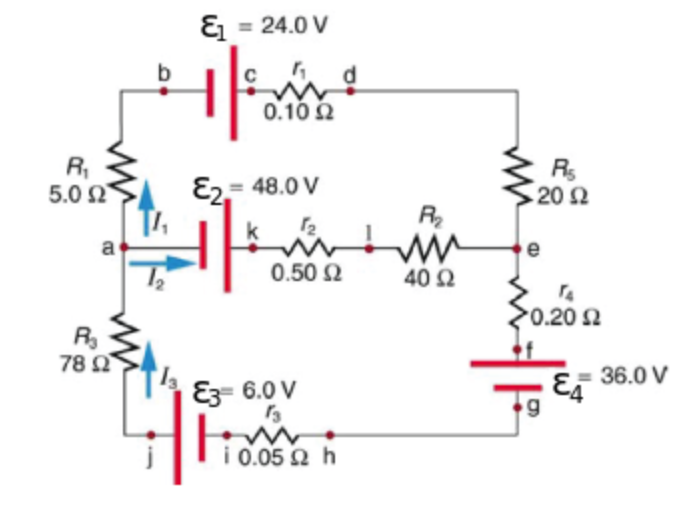
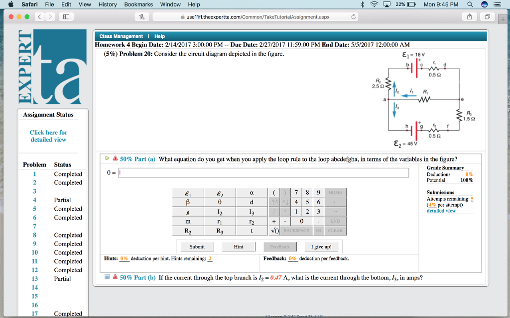
For the circuit shown in Figure P28.32 , we wish to find the currents I1,I2, and I3 . Use Kirchhoff's rules to obtain equations for (a) the upper loop, (b) the ...4 answers · Top answer: Yes. Question were given this circuit there. It's parts in this question. So in part A ... 91% (345 ratings) Problem Details. Consider the circuit diagram depicted in the figure. Part (a) What equation do you get when you apply the loop rule to the loop abcdefgha? Part (b) If the current through the top branch is I2 = 0.49 A, what is the current through the bottom I3, in amps? Frequently Asked Questions. Jul 7, 2021 — Consider the circuit diagram depicted in the figure. {1= 18V 0. 52 2.523 om 3R 31.5.22 0.52 Ez = 45V What equation do you get when you apply ... εί Consider the circuit diagram depicted in the figure. It is known that two 25Ω 24V and ε2 36V. R2 and R3-40f, but Ri is unknown. Caution: Current directions.
Two Stage Sallen Key Topography Fourth Order Bessell Filter With A 2 Download Scientific Diagram
So we have this circuit here and we want to do is we want to rank thes potential differences going across these resistors, so we wanna rank them from largest to smallest. So what we can do first is we can go ahead and find the equivalent resistance of these two branches here. So the equipment resistance R two R three and r four. When we go ahead and salt for that, we'll find an equivalent ...
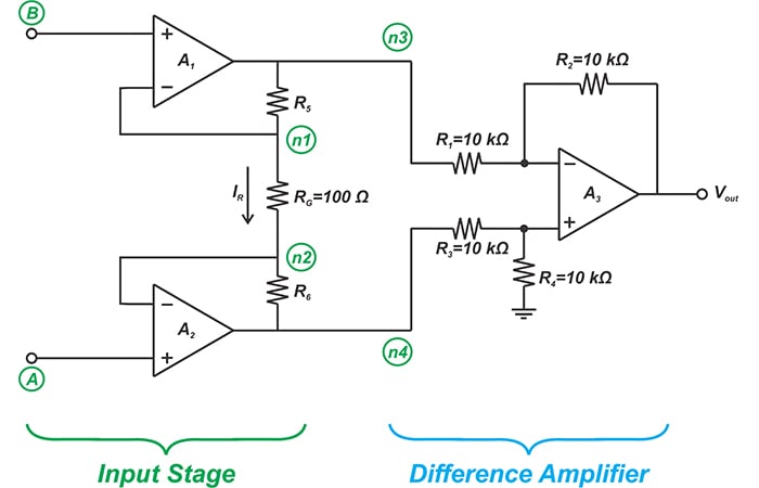
Learn About Three Op Amp Instrumentation Amplifiers Technical Articles
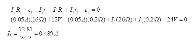
Consider the circuit diagram depicted in the fgure. It is known that two battery internal resistors r1and r2 are both 0.2Ω· = 12V and & = 24V. R2 16Ω 2. and Rs 262, but Ri is unknown. Caution: Current directions.

Introduction To Network Transformation On Aws Part 2 Networking Content Delivery
The open-circuit voltage / short-circuit current approach can be used to calculate the Thevenin equivalent for a known circuit. Consider the circuit from slide 4: + - V S R 1 R 2 I S 9V 6 mA 1.5 k! 3 k! Open-circuit voltage - Use whatever method you prefer. We'll use node voltage in this case. + - V S R 1 R 2 I S v a + - v oc YRF= YD ...
Solved Consider The Circuit Depicted In The Diagram If The Chegg Com
6.36 Figure 6.21 shows a block diagram of a ROM.Acircuit that implements a small ROM, with four rows and four columns, is depicted in Figure P6.3. Each X in the figure represents a switch that determines whether the ROM produces a 1 or 0 when that location is read. (a) Show how a switch (X) can be realized using a single NMOS transistor.

Resources Powersim Inc
2. 27.3.2 (7, ex) Consider the circuit diagram depicted in the figure. (a) What equation do you get when you apply the loop rule to the loop abcdefgha, in terms of the variables in the figure? (b) If the current through the top branch is I2 = 0.085 A, what is the current through the bottom, I3, in amps? (c) Find the current through R 1 and the resistance of R 1.
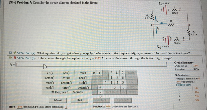
Solved 8 Problem 7 Consider The Circuit Diagram Depicted Chegg Com
(4%) Problem 22: Consider the circuit diagram depicted in the figure:81 = 18V0.5 0250=1,5 00.5 !82 45V50% Part (a) What equation do you get when you apply ...5 answers · 5 votes: (a) Write the loop rule for two different loops in the circuit shown in Figure $P 16.30$ ...

10 Problem 1 Consider The Circuit Diagram Depicted In The Figure Docx 10 Problem 1 Consider The Circuit Diagram Depicted In The Figure 1 592 Course Hero
Physics. Physics questions and answers. Consider the circuit diagram depicted in the figure. What equation do you get when you apply the loop rule to the loop abcdefgha? If the current through the top branch is I_2 = 0.49 A. what is the current through the bottom, I_3, in amps? Question: Consider the circuit diagram depicted in the figure.
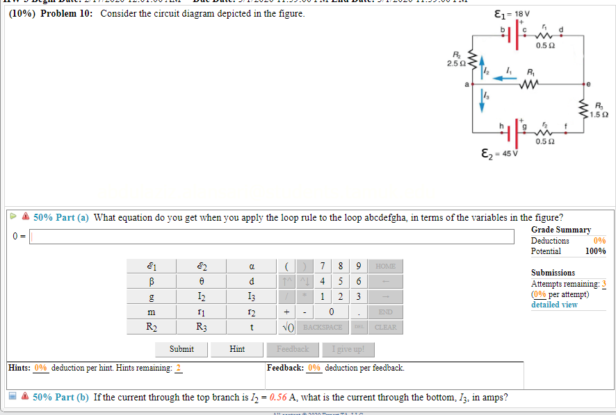
Solved 10 Problem 10 Consider The Circuit Diagram Chegg Com
P 5.2-2 Consider the circuit of Figure P 5.2-2. Find i a by simplifying the circuit (using source transformations) to a single-loop circuit so that you need to write only one KVL equation to find i a. Figure P 5.2-2 . Solution: Finally, apply KVL: 16 10 3 4 0 2.19 A aa 3 a
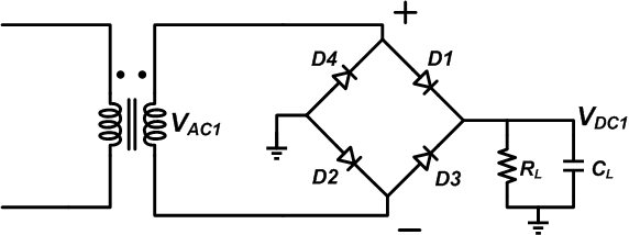
How To Troubleshoot A Diode Bridge Rectifier Technical Articles
Transcribed image text: Consider the circuit diagram depicted in the figure. What equation do you get when you apply the loop rule to the loop abcdefgha, in terms of the variables in the figure? If the current through the top branch is I_2 = 0.47 A, what is the current through the bottom.

Do 254 Intro Compliance Free Tools Papers Resources Afuzion
For the action depicted in the figure, (Figure 2) indicate the direction of the induced current in the loop (clockwise, counterclockwise or zero, when seen from the right of the loop). The face of the south pole will become the north pole, so there will be a force of attraction between them, which makes the motion of the coil opposed.
Answered Consider The Circuit Diagram Depicted Bartleby
Consider the simple circuit shown in Figure 2 where a 9V battery is connected to a 10 load. Figure 2 What is the value of the load current? _____ How much power is dissipated in the load? _____ P = I 2 R Watts Knowing the battery voltage and the current that is being drawn from the battery, what is the power delivered by the source? _____ Does the power delivered by the source equal the power ...
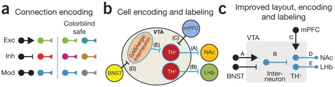
Neural Circuit Diagrams Nature Methods
Figure 6.13. State-assigned table for the sequential circuit in Figure 6.12. Present Next state state Outputs A 00 00 0 1 0 0 0 0 0 0 0 B 01 10 1 0 0 0 1 0 0 1 0 C 10 11 1 1 1 0 0 1 0 0 0 D 11 00 0 0 0 1 0 0 1 0 1
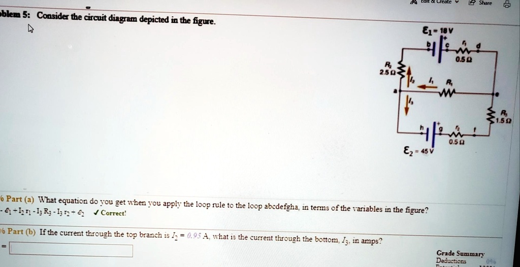
Solved Late 1 Share Bken 5 Consider The Circuit Diagrem Depicted In Te Figure 61 Iv 050 25 150 0 54 82 A5v Part A Wzat Equation Do To1 Get When You Apply
Transcribed image text: (10%) Problem 5: Consider the circuit diagram depicted in the figure 0.5 Ω R2 2.5 Ω /2 R 1.5Ω 0.5 Ω 50% Part (a) what equation do you get when you apply the loop rule to the loop abcdergha, in terms of the variables in the figure? Grade= 100% Correct Answer Student Final Submission Feedback Correct! 012 R2+ 112 T3 R3 +32-62 0- 1-(Ti +R2) I2+(R3r2)13 2 Grade Summary ...
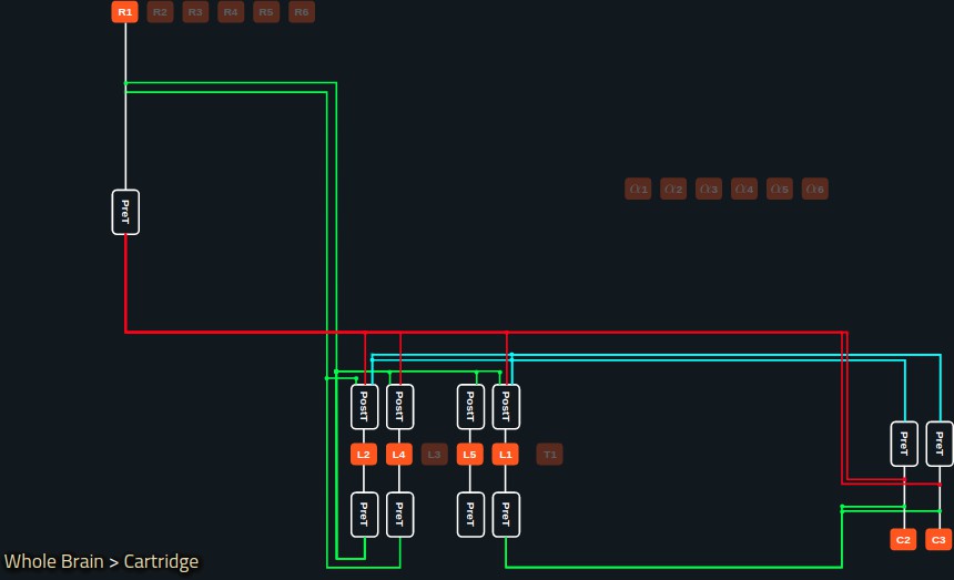
Accelerating With Flybrainlab The Discovery Of The Functional Logic Of The Drosophila Brain In The Connectomic And Synaptomic Era Elife
For the circuit shown in the figure, calculate (a) the current in the 2.00-Ω resistor and (b) the potential difference between points a and b, ΔV = Vb - Va.
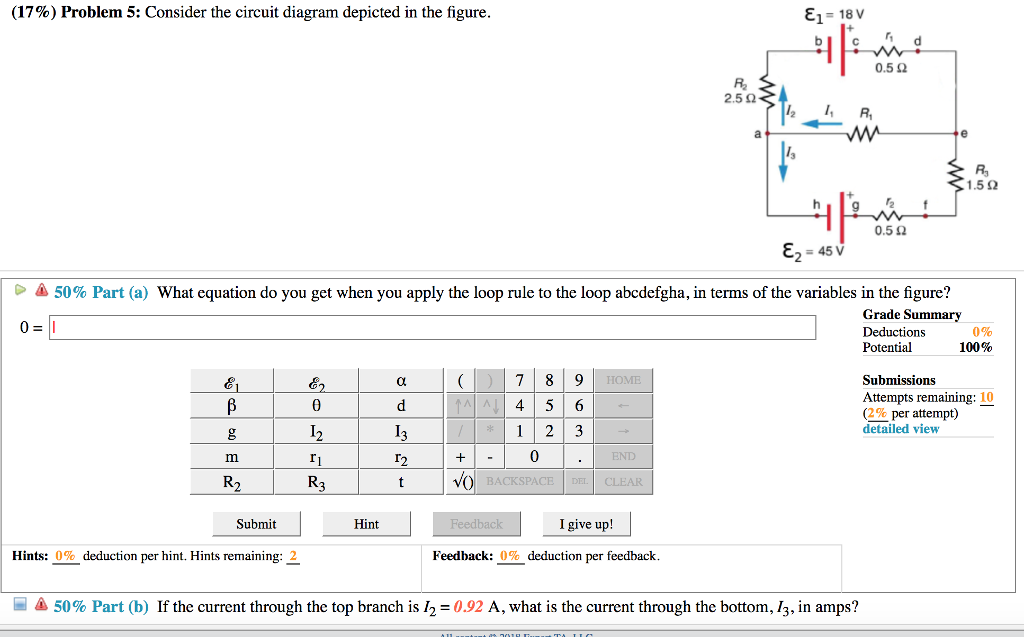
Solved 17 Problem 5 Consider The Circuit Diagram Chegg Com
Sample Circuit We consider the ... Consider the circuit shown in Figure P28.9. Find (a) the current in the 20.0-Ω resistor and (b) the ... Draw the circuit diagram and assign labels and symbols to all known and unknown quantities. Assign directions to the currents.

10 Problem 1 Consider The Circuit Diagram Depicted In The Figure Docx 10 Problem 1 Consider The Circuit Diagram Depicted In The Figure 1 592 Course Hero
Figure 12.2.2 (a) Time dependence of IR (t) and VR (t) across the resistor. (b) Phasor diagram for the resistive circuit. The behavior of IR (t)and can also be represented with a phasor diagram, as shown in Figure 12.2.2(b). A phasor is a rotating vector having the following properties: VR (t) (i) length: the length corresponds to the amplitude.

The Logic Circuit Diagram Of 4 2 Encoder Download Scientific Diagram
Consider the circuit diagram depicted in the figure. Now apply the loop rule to loop 1 the larger loop spanning the entire circuit. Assume that v 128 v r1 r2 r3 r4 r5 200 ω. B if the current through the top branch is i 2 0605 a. Consider a series rc circuit as in the figure below for which r 100 mω c 500 µf and ε 300 v.

Modeling And Simulation Of Power Distribution System In More Electric Aircraft

Ideal Current Source An Overview Sciencedirect Topics

Experimental Investigation On Pre Heating Technology Of Coal Water Slurry With Different Concentration In Shell And Tube Heat Exchangers With Ladder Type Fold Baffles Sciencedirect

Pdf The Gate Theory Of Pain Revisited Modeling Different Pain Conditions With A Parsimonious Neurocomputational Model
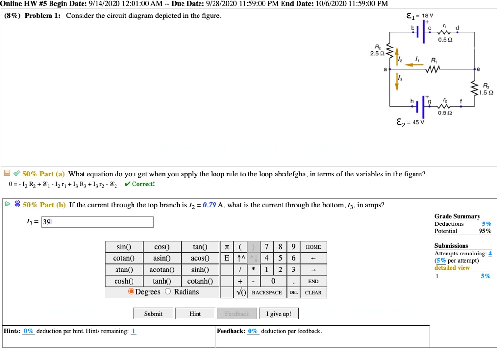
Solved Online Hw 5 Begin Date 9 14 2020 12 01 00 Am Due Date 9 28 2020 59 00 Pm End Date 10 6 2020 1 59 00 Pm 8 Problem 1 Consider The Circuit Diagram Depicted In The Figure 81
Architecture Agnostic Algorithm For Reconfigurable Optical Interferometer Programming
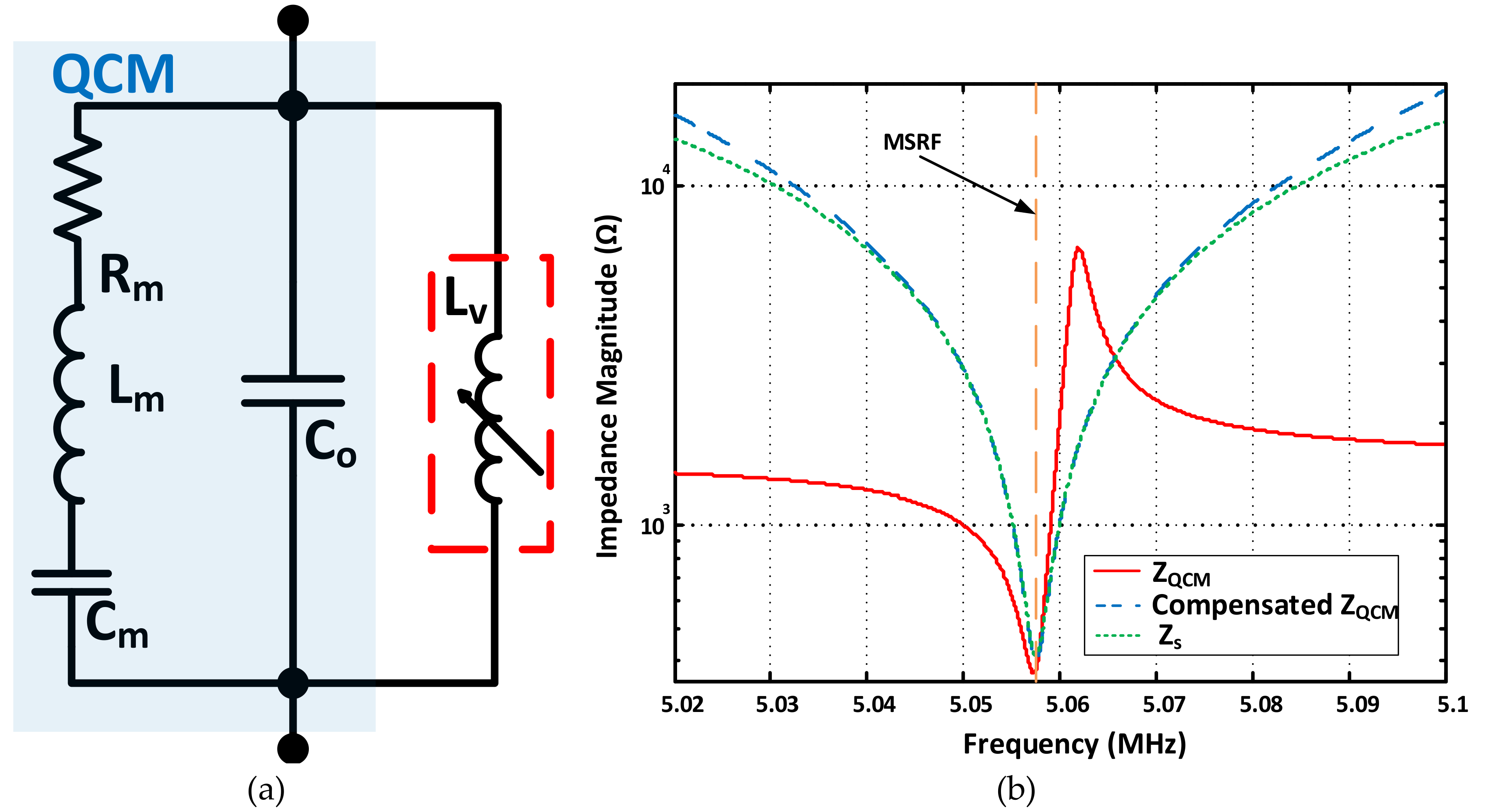
Sensors Free Full Text Quartz Crystal Microbalance Electronic Interfacing Systems A Review Html
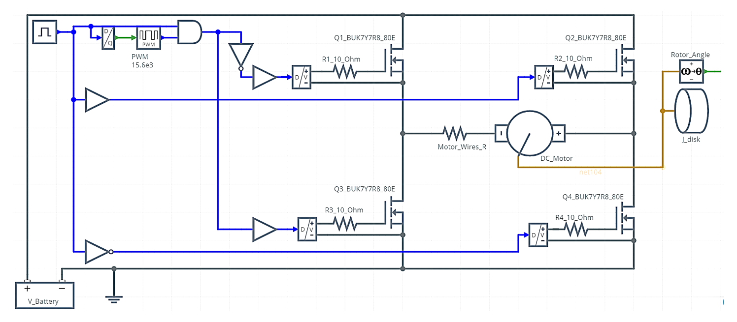
Using Power Mosfets In Dc Motor Control Applications Nexperia
Solved Consider The Circuit Diagram Depicted In The Figure Chegg Com

Resources Powersim Inc

A 12 B 10 Gs S Interleaved Pipeline Adc In 28 Nm Cmos Technology Analog Devices

10 Problem 1 Consider The Circuit Diagram Depicted In The Figure Docx 10 Problem 1 Consider The Circuit Diagram Depicted In The Figure 1 592 Course Hero

10 Problem 1 Consider The Circuit Diagram Depicted In The Figure Docx 10 Problem 1 Consider The Circuit Diagram Depicted In The Figure 1 592 Course Hero
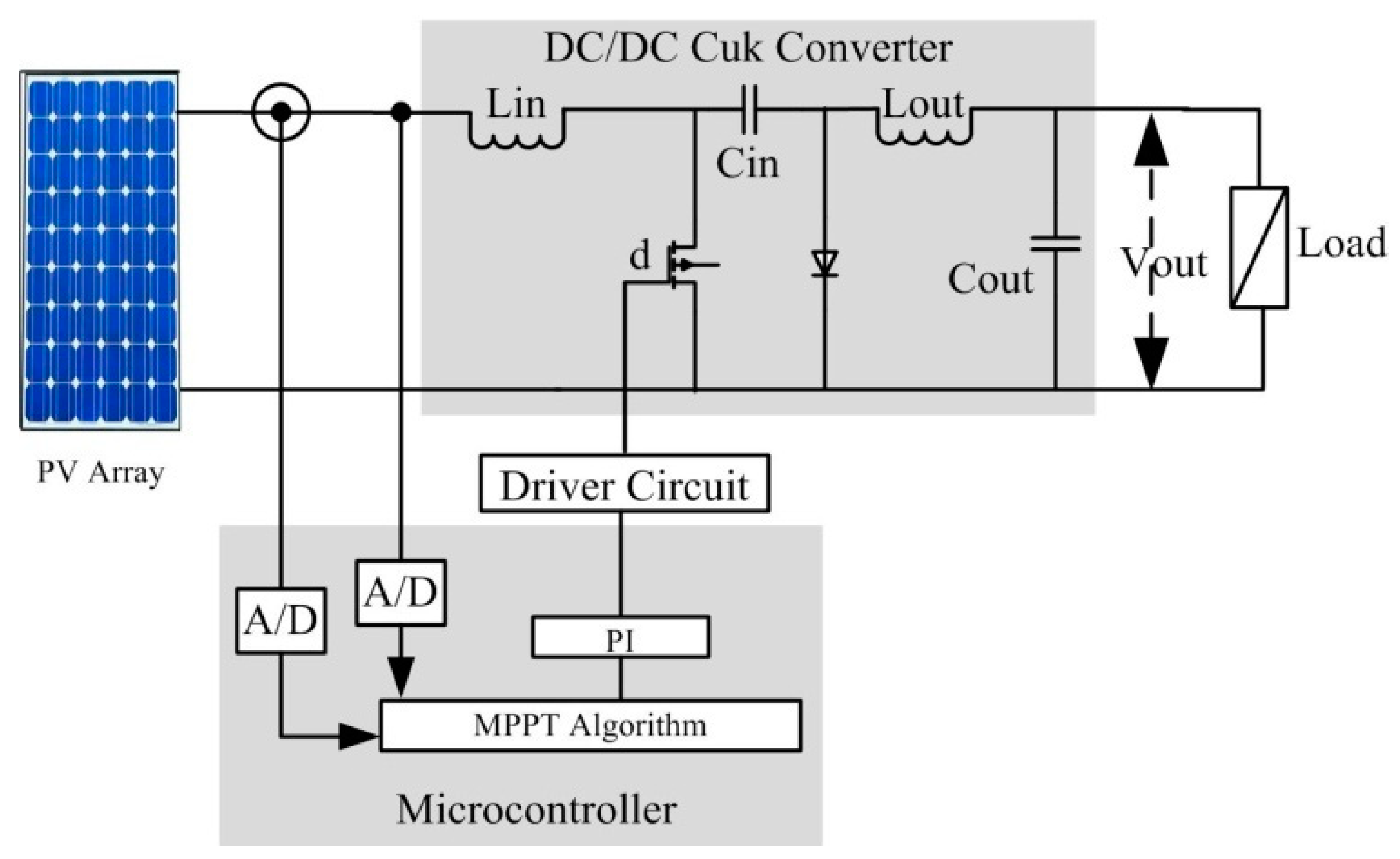
Electronics Free Full Text A Comprehensive Review On A Pv Based System To Harvest Maximum Power Html
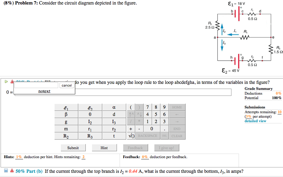
Solved 8 Problem 7 Consider The Circuit Diagram Depicted Chegg Com

Chemoresistive Materials For Electronic Nose Progress Perspectives And Challenges Park 2019 Infomat Wiley Online Library

Modeling And Design Of Single Phase Pv Inverter With Mppt Algorithm Applied To The Boost Converter Using Back Stepping Control In Standalone Mode

Do 254 Intro Compliance Free Tools Papers Resources Afuzion
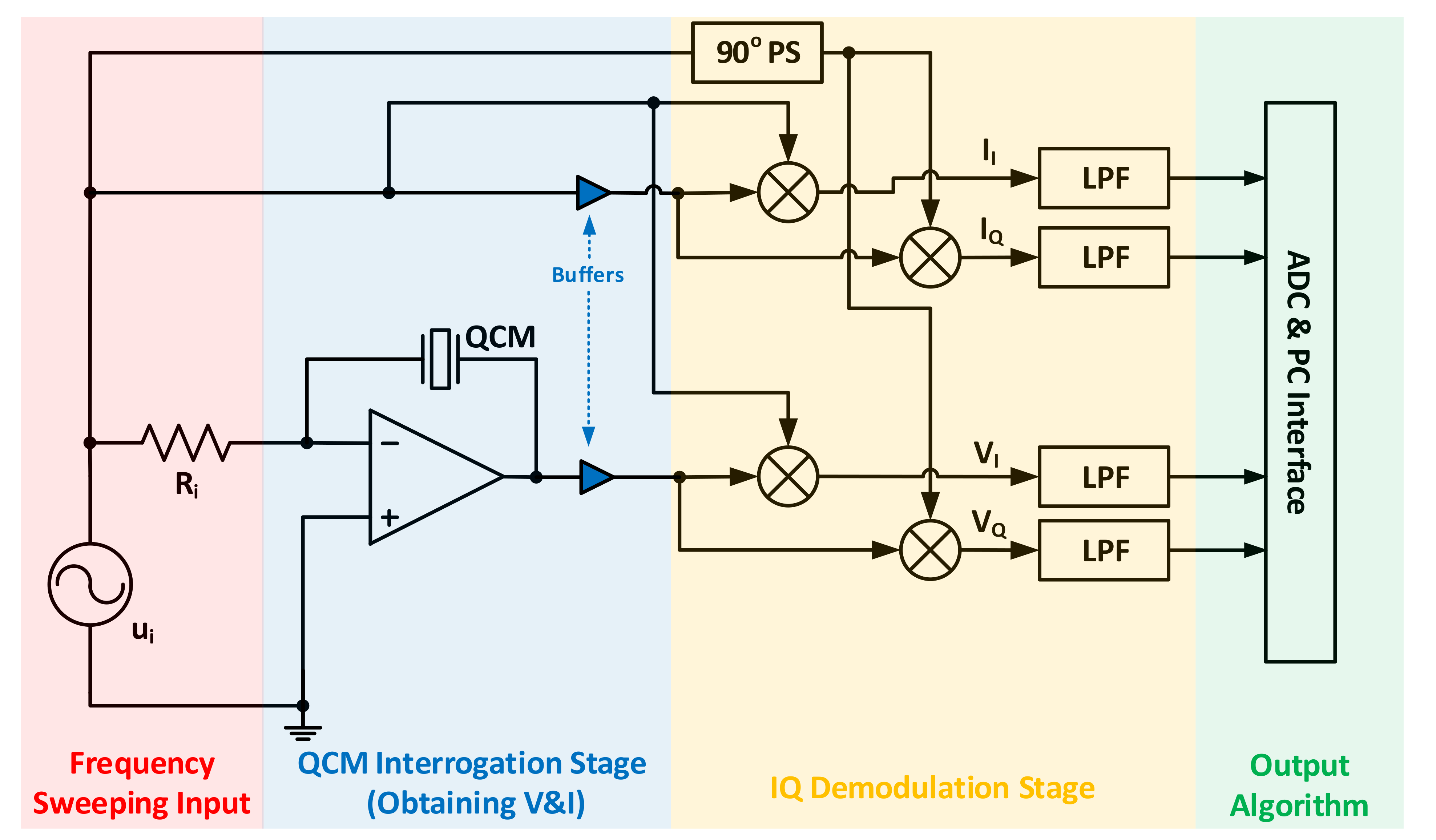
Sensors Free Full Text Quartz Crystal Microbalance Electronic Interfacing Systems A Review Html

Basic Pneumatic Circuits Tech Briefs

State Transition Diagram An Overview Sciencedirect Topics

Refer To The Circuit Diagram Depicted In Figure 1 Below 10245v 20 20v 3 4021 10 22 Homeworklib

Basic Pneumatic Circuits Tech Briefs

Energies Free Full Text Experimental Evaluation Of An Innovative Non Metallic Flat Plate Solar Collector Html
0 Response to "41 consider the circuit diagram depicted in the figure"
Post a Comment