41 boat fuel system diagram
30 Jan 2019 — Boat Fuel System Troubleshooting. Some boaties will tell you that if you're having any kind of trouble with your outboard motor, 95% of the time ... Fuel System Diagram Update July 2013 Additions, Revisions, or Updates Publication Number / Title Platform Section Title Change DDC-SVC-MAN-0082 EPA10/ GHG14 DD Platform Fuel System (Without MCM Heat Exchanger) – Two-Filter System Callouts updated. Fuel System (With MCM Heat Exchanger) –Two-Filter System 7 08-13
Step 1: Fill out pump finder above. Step 2: Add the pump to your cart. Step 3: Refer to the diagram on the product page for plumbing or refer back to this page and click the link to your fuel pump diagram. Step 4: Bulk add to cart! The following are the basic solutions to the most common systems. - For more specific variables please call tech at 913-647-7300

Boat fuel system diagram
For permanently installed fuel tanks on boats, EPA has adopted a phase-in that begins July 31, 2011. In the period from July 31, 2011 through July 31, 2012, 50 percent of the U.S. market boats produced by each company must meet the diurnal standard and beginning August 1, 2012, all marine fuel tanks and boats must meet the diurnal emission ... 25 Jun 2019 — labelled diagram of a fuel system installation ... The ABYC specifies that permanent tanks must be grounded, vented to the outside, ... Fuel Systems (Marine) Voltage - "I" to "G" terminal - 10 to 16 volts. 52 results. Test gauge as follows: Connect . Fuel Gauge. Check the wiring diagram that comes with the kit and mark the back of the new fuel gauge with symbols for each post: “S” for the sender, “G” or “—” for the ground, and “I” for the ignition.
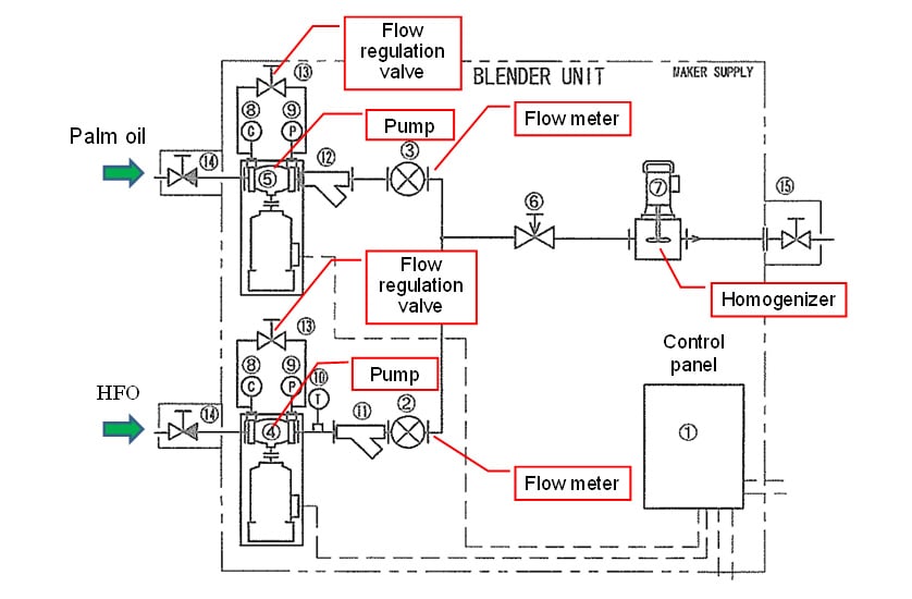
Boat fuel system diagram. if no more than five ounces of fuel is discharged in 2 1/2 minutes when: (A) The hose is severed at the point where maximum drainage of fuel would occur, (B) The boat is in its static floating position, and. (C) The fuel system is filled to the capacity market on the tank label. Then you may use Type B1-15. Basic layout. No fuel fill shown, No tank crossover shown, No vent system shown. Additional gear ontop of primary filer optional fuel polishing. Marine vent systems have a HIGH SPEED vent for refueling that is closed to run and low speed venting for operating at sea. Two fuel fills are normally used for two tanks. Parts, Rule 1500 GPH Automatic Parts, Inflatable Fuel Pump And Fuel Line For Mercury Hp Wiring Diagram Full Size category archives outboard service repair ... Fuel Oil System Diagram on Ship with Diagram Marine Diesel Engine. In the system shown in Figure, the oil from the service tank flows through a three-way valve to the supply pump. After that it goes to the mixing column through a filter and flow meter. A flow meter is fitted into the system to indicate fuel consumption.
boats. This means that evaporating fuel can reach an explosive mixture with the surrounding air, inside an enclosed space. Any sort of ignition can then cause a real disaster. The sketch in figure 1 provides an overview of the basic requirements for a safe fuel system. Now the job of the fuel system does not sound too difficult. The system also needs to be designed to prevent the defeat of the tank ventilation system when parking a trailered boat on a steep hill, when fuel in the tank might back up into the vent hose. Some new marine fuel systems carry charcoal canisters similar to those found in primary fuel tank vent systems in the automotive world. Boat Building Regulations | Boat Fuel System | Fuel Tank Diagram. The Fuel Systems section of this website may be purchased and downloaded. It is in PDF format and payment is through PAYPAL Go to the store here $9.99 USD. Fuel Systems (Marine) Voltage - "I" to "G" terminal - 10 to 16 volts. 52 results. Test gauge as follows: Connect . Fuel Gauge. Check the wiring diagram that comes with the kit and mark the back of the new fuel gauge with symbols for each post: “S” for the sender, “G” or “—” for the ground, and “I” for the ignition.
25 Jun 2019 — labelled diagram of a fuel system installation ... The ABYC specifies that permanent tanks must be grounded, vented to the outside, ... For permanently installed fuel tanks on boats, EPA has adopted a phase-in that begins July 31, 2011. In the period from July 31, 2011 through July 31, 2012, 50 percent of the U.S. market boats produced by each company must meet the diurnal standard and beginning August 1, 2012, all marine fuel tanks and boats must meet the diurnal emission ...
Five Oceans EPA Fuel Line Kit for OMC, Johnson & Evinrude, 6 ft x 5/16 inches Hose FO-4517 Fuel Tanks,Boat Engine Parts with 60% off discount - www.klevering.com

860-880 North Lake Shore Drive, Electrical Riser Diagram (11/28/1949) // Ludwig Mies van der Rohe (American, born Germany, 1886–1969) Associate Architect: Holsman, Holsman, Klekamp and Taylor (American, 20th century) Associate Architect: Pace Associates (American, 20th century) Structural Engineer: Frank J. Kornacker (American, active 1940s–1950s)


0 Response to "41 boat fuel system diagram"
Post a Comment