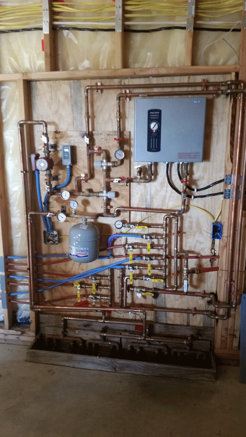
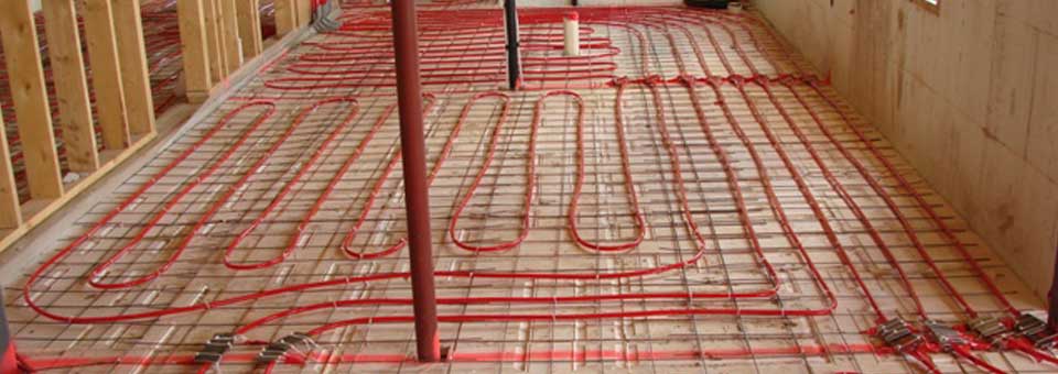
38 hydronic heating system diagram
Central heating diagram - Mike the Boilerman This diagram illustrates how simple the heating system connected to a combi boiler is. No external pump, no tanks, no external expansion vessel, no motorised valves and in many cases item 6 is not needed either. (An automatic bypass valve is fitted inside most combi boilers by the manufacturer these days.) PDF Modern HydronicSystem Designs for Condensing Boilers (boiler) and secondary (system) loops -Closely spaced tees or a mixing manifold • Prevents flow in one circuit from interfering with another -Example: As zone valves open, close, or modulate, and as system pumps vary speed, the boiler loop is not impacted. Monday, December 01, 2014 Modern Hydronic Designs For Condensing Boilers 7
Hydronic Heating Systems Examples. Installation Example of ... Heating Mixing Valve Setup. How to Size Copper Tees for Hydronic Heating Systems. Using Zone Valves and Circulating Pumps in a Heating System. Using Sharkbite Fittings in Plumbing and Heating Systems Installations. Water to Air Heat Exchangers (Finned Coil Heat Exchangers) Wire Diagram for Taco Zone Valves. Taco Pump Piping Example.

Hydronic heating system diagram
Wire Diagram for Taco Zone Valves for Hydronic Heating Systems Wire Diagram for Taco Zone Valves. Taco Zone Sentry Zone Valves provide on-off, normally open or normally closed control in both open and closed hydronic systems. The valves can be used in a wide variety of heating and non-condensing cooling applications, primarily designed for use with baseboard, fan coils, radiators, convectors, air handlers ... PDF BASIC HYDRONIC SYSTEM DESIGN - ctashrae.org BASIC HYDRONIC SYSTEM DESIGN Generation Equipment Boilers, Chillers, Cooling Towers, WWHPs, etc. Terminal Units Fan Coils, Chilled Beams, Finned Tube, Radiant, etc. Decoupler Primary Pumps Closely Spaced Tees P-1 & P-2 Distribution Piping Air / Dirt Separator Expansion Tank Secondary Pumps P-B-1 & P-B-2 2 REFERRING TO PUMPS HEATING PDF Hydronics - Step By Step - TACO - HVAC • Universal hydronics formula -GPM = BTUH ÷ΔT x 500 • Headloss - Zone length x 1.5= total developedlength - Multiplier accounts for valvesand fittings - Developed length x .04= head loss -4feet of head for every 100 feet of pipe Let's Do One… • Size the zone piping: - 27,000 BTUH load, 200ΔT, 100% water • GPM = GPM = 2.7
Hydronic heating system diagram. PDF ZONING HYDRONIC SYSTEMS - Caleffi a zoned heating system is not necessarily determined solely by the number of zones it has. Zoning has been used in hydronic systems for decades, as evidenced by the piping diagrams in figures 1-1 and 1-2. Source: ITT Bell & Gossett Handbook, 2nd Edition (1949) Source: ITT Bell & Gossett Primary Secondary Pumping Application Manual (1968) 5: Schematic of a Hydronic Heating System [4] | Download ... It has been shown that the heating, ventilation, and air conditioning (HVAC) systems of commercial buildings can offer ancillary services to power systems without loss of comfort. In this paper, we... Piping layouts to avoid in hydronic systems - HPAC Magazine The system shown in Figure 1 accurately represents a drawing that I received. Aside from the "morphed" piping layout, there are several other details that should be of concern: There are no check valves in the load circuits to prevent reverse flow when some loads are active while others are not. There are no purging valves in the load circuits. PDF Hydronic System Design Manual - GARN Hydronic System Design Manual ©DECTRA CORPORATION - March 2013 8 FORCED AIR HEATING: DO NOT MOUNT A HOT WATER COIL ON THE RETURN SIDE OF THE FURNACE. Warm air will be flowing over the blower motor and may not provide sufficient motor cooling. Doing so will void the furnace warrantee and the UL listing of the furnace.
Ode to hydronic boat heating, and Sure Marine Service - Panbo However, a marine hydronic heating system is not just a boat-size boiler (my little one is also marketed as the Webasto Thermo Top C and apparently used in over a million trucks). Not even close. As suggested in the Sure Marine diagram above, there are many components to even a fairly basic system. For instance, the boiler needs external air ... PDF I. PIPING DIAGRAMS - Water and Space Heating 10. Mixing valves are recommended on all tanks if hot water temperature is above 119oF. 11. Expansion tank must be rated for use with potable water. 12. Use either indirect/tank sensor or system/pipe sensor mounted on common return to the boiler. 13. Aquastat or system/pipe sensor connects to DHW sensor input on boiler. Piping Layouts for Hydronic Heat - JLC Online In a series circuit, the simplest hydronic piping system, the radiators and boiler are on one common loop. Radiators near the end of the loop are often larger to compensate for the lower water temperature. In the simplest hydronic distribution system, all heat emitters are connected into a common loop, or "circuit," with the heat source. HYDRONIC HEATING: Schematics & Video On How to Use a Tank ... Click the images below to download detailed schematic drawings for connecting a tank-style water heater to drive hydronic heating systems. One schematic is for the simple system, and the other is for the more complex heat exchanger option. Click to download schematic for installing a simple tank-style space heating system
Big leak with hydronic heating system | Eichler Network Abandoning radiant heat? Some will to put in a Unico system. Some have gone to hydronic heating systems where you run it just under the beams throughout the house. Hydronic is piped hot water with little fans. Similar to the old radiator heat. This goes in the ceiling, but you only get heat. It's expensive. Hydronic Heat Pumps: The New HVAC Wave Check out this diagram from Mitsubishi Electric's website: Benefits of Hydronic Heat Pumps Efficiency Because heat pumps move heat rather than create heat, they can transfer 300 percent more energy than they consume. Using water to heat your home requires less energy and provides higher efficiency than traditional HVAC systems. Heating System Circulator Pump Location & Mounting The hydronic heating system is relying on the starting water pressure in the heating system to provide enough lift to get hot heating water into baseboards, convectors, or radiators in the upper floors of the building. Typically the cold starting pressure in a heating system is 12 psi, provided by . the Water Feeder Valve On the boiler. A Beginners Guide to Hydronic Heating The basic components of a boiler, liquid, plumbing manifold, tubing, and heat exchanger are the essentials, but there are several ways that this system can be installed and operated. From tankless water heaters to radiant floors to outdoor hydronic heat, you will be able to find a way to meet your home heating needs.
Hydronic Heating Boilers - Hot Water from A. O. Smith Hydronic Heating Boilers Description Series Piping Diagram PDF Piping Diagram DWG Genesis® One Boiler Primary, Secondary Hydronic Heating System GB 300 2500 AOSHG61080 AOSHG61080 Genesis® Two Boilers Primary, Secondary Hydronic Heating System GB 300 2500 AOSHG61081 AOSHG61081 Genesis® Three Boilers
PDF Small-Scale Hydronic Cooling - IAPMO Small-Scale Hydronic Cooling Authored by John Siegenthaler Hydronic technology has long been known for providing unsurpassed heating comfort. Indeed, the vast majority of the hydronic systems now installed in homes and light-commercial buildings provide space heating, and in some cases, domestic water heating. Few currently provide cooling.
Hydronic Heating System Control and Wiring diagram-MHSDS-5 Description This payment is for release of electrical control interconnections drawings for hydronic heating system controls purchase from Modular Hydronics Shop and related to design number ID assigned to your project. This charge cannot be applied to alternate projects. Price per 10 square feet of total floor plan.
Boiler Piping Diagram For Radiant Heat - schematron.org Wiring Diagram Roth Shunt Systems Boiler with Heat Exchanger and Variable Speed Injection Pump Using the Chart. The photo above is our "Radiant Ready A/T" single zone Closed System for use with an on-demand water heater. This pre-assembled, panel system comes right out of the box just as you see it here, including pump, pre-wired controller ...
PDF UNDERSTANDING HOT WATER SYSTEMS IN THE HOME Dec13 - APHC The diagram below shows the general layout of an unvented hot water system: Instantaneous hot water heating systems This method involves using gas or electricity to heat the water to a useable temperature without the need to store the water. The electric versions use a coiled heating element to heat the water rapidly in a
Smartheat - One stop Heating and Cooling Design Group SmartHeat is smart! Smart for environmentally advanced solutions for heating and solar hot water systems. We used them for our under-floor heating and heat pump systems for both domestic hot water and heating the floor system, all connected to our solar hot water system, as well.
PDF System Diagrams - Central Boiler System Diagrams H C M R Water Heater Hot Supply from Outdoor Furnace Return 10 gpm 10 gpm 10 gpm 5 gpm 5 gpm Bleeder Screw 4 x Pipe Dia. Max. Zoning Pump Multi-Heater Option Water-to-Water Heat Exchanger Hot Supply from Pump on Outdoor Furnace This horizontal assembly must not exceed a height of 4 inches above top of water heater.
Basic Hydronic Heating Components and Their Role in A System Hydronic System Component Names The basic system in this illustration is found throughout the world today. It is a residential or light commercial hydronic air handler connected to a water heater. The circuit for the air handler is tied in with the domestic hot water system. The circulator pump moves water through the air handler loop.


0 Response to "38 hydronic heating system diagram"
Post a Comment