42 how to read ttt diagram
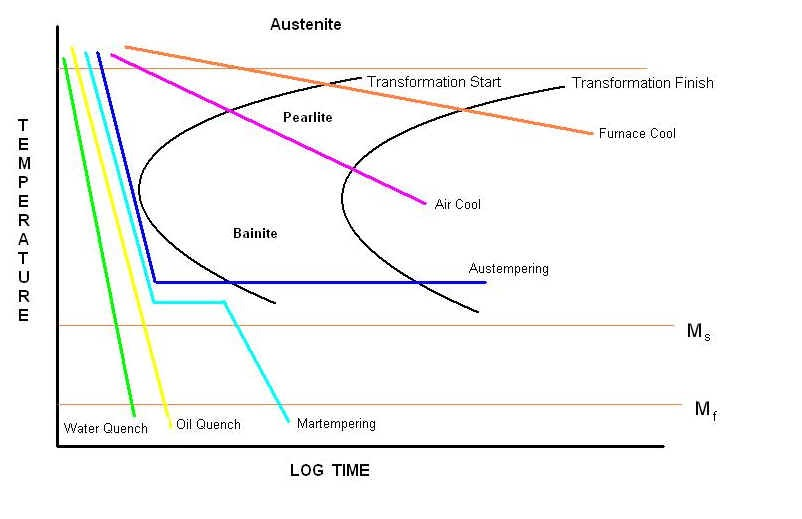
PDF Time-Temperature-Transformation (TTT) Curves ttt diagram is a plot of temperature versus the logarithm of time for a steel alloy of definite composition. ttt diagram indicates a specific transformation starts and ends and it also shows what percentage of transformation of austenite at a particular temperature is achieved. the aims of ttt diagrams is determined type of structure for and … en.wikipedia.org › wiki › Heat_treatingHeat treating - Wikipedia Time-temperature transformation (TTT) diagram for steel. The red curves represent different cooling rates (velocity) when cooled from the upper critical (A3) temperature. V1 produces martensite. V2 has pearlite mixed with martensite, V3 produces bainite, along with pearlite and martensite.
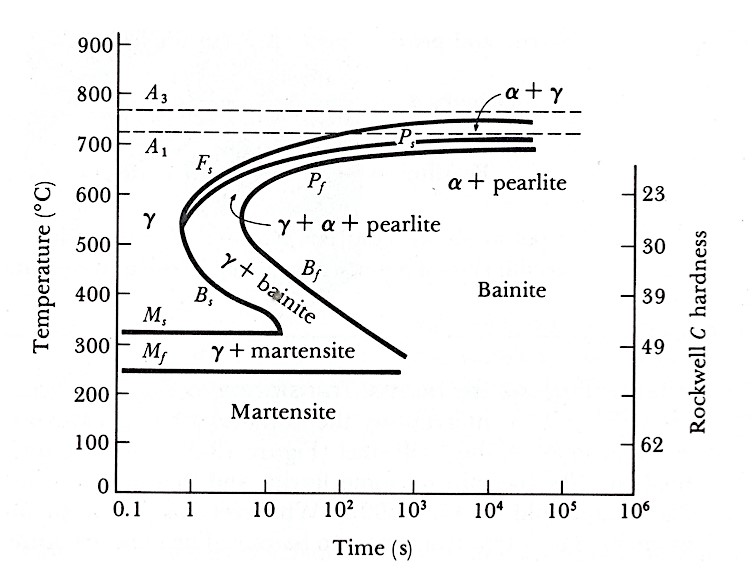
The Time-Temperature-Transformation Curve - Gear The TTT diagram is really a simplified diagram of the kinetics of pearlite and bainite formation, and the diffusion-less transformation of martensite. It is a diagram of overlapping curves (Figure 6). The shape and position of the curves depend on the alloy composition, grain size, and carbon content.

How to read ttt diagram
Examples of steel microstructures using a TTT diagram ... Here we show a variety of different steel microstructure outcomes depending on different TTT diagram heat treatments. TTT diagram - SlideShare TTT Diagram • On the other hand, TTT diagram is a more practical diagram. • It shows what structures can be expected after various rates of cooling. • It graphically describes the cooling rate required for the transformation of austenite to pearlite, bainite or martensite. Solved Please Explain How To Read Ttt Diagrams - Free ... Time Temperature Transformation (TTT) diagram. Just Now Is the TTT diagram, so called, because it represents the time taken at any given temperature for a given fraction of the transformation to get completed.The typical TTT diagram is a C shaped curve. In this case, we have used it to represent, at any given temperature, the time required for 1% transformation to complete.
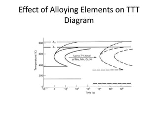
How to read ttt diagram. TTT Diagrams: Introduction and Limitations | Material ... ADVERTISEMENTS: In this article we will discuss about:- 1. Introduction to TTT Diagrams 2. Effect of Alloying Elements on TTT Curve 3. Limitations. Introduction to TTT Diagrams: Solid state transformations, which are very important in steels, are known to be dependent on time at a particular temperature, as shown in figure. Isothermal transformation diagram, also […] TTT Diagrams 4. Experimental Construction of TTT and Phase ... Phase diagrams at low temperatures are therefore a bit tentative on occasion. For phase and TTT diagrams the temperature of your sample should be the same everywhere. This is easier to achieve with small samples. Measuring whatever you measure, however, is always more difficult with small samples. Iron Carbon Ttt Diagram - schematron.org The Fe-C phase diagram is a fairly complex one, but we will only consider the steel part of the diagram, up to around 7% Carbon. Iron Carbon Phase Diagram, TTT Diagram, CCT Diagram Slideshare uses cookies to improve functionality and performance, and to provide you with relevant advertising. How to Read Time Temperature Transformation Diagrams ... TTT diagrams have time on the x-axis and temperature on the y-axis. The lines on a TTT diagram represent points at which a material transforms from one phase or microstructure to another. Sometimes the lines are labeled with percentages, which represent the percentage of the material that has transformed.
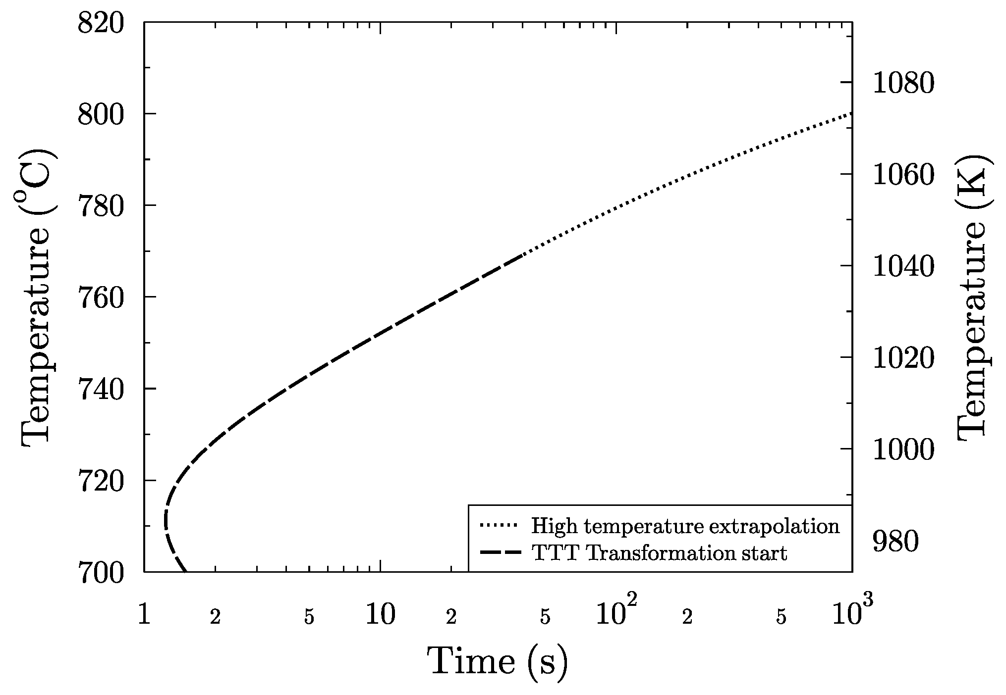
Transformation Diagrams (CCT & TTT) - SIJ Time-temperature transformation (TTT) diagrams Measure the rate of transformation at a constant temperature. In other words a sample is austenitised and then cooled rapidly to a lower temperature and held at that temperature whilst the rate of transformation is measured, for example by dilatometry. TTT Diagram Basic - TTT diagram for steel, eutectoid steel Thus, the TTT diagram indicates transformation products according to temperature and also the time required for complete transformation. Curve 1 is transformation begin curve while curve 2 is the transformation end curve. The region to the left of curve 1 corresponds to austenite (A'). › teacher_modules › Sets_and_venn_diagramsSets_and_venn_diagrams In a Venn diagram, the universal set is generally drawn as a large rectangle, and then other sets are represented by circles within this rectangle. For example, if V = { vowels }, we could choose the universal set as E = { letters of the alphabet } and all the letters of the alphabet would then need to be placed somewhere within the rectangle ... sv.internautasporlapaz.org sv.internautasporlapaz.org
Quiz & Worksheet - TTT Diagram | Study.com The use of time temperature transformation (TTT) diagrams is the focal point of this quiz and worksheet combo. The quiz will ask you about another name for a TTT diagram, along with a question ... TTT Diagram - Metallurgy for Dummies Time-Temperature-Transformation (TTT ) Diagram T (Time) T (Temperature) T (Transformation) diagram is a plot of temperature versus the logarithm of time for a steel alloy of definite composition. It is used to determine when transformations begin and end for an isothermal (constant temperature) heat treatment of a previously austenitized alloy. TTT Diagrams: 1. The Basic Idea - Technische Fakultät In a TTT diagram the first line denotes always that 1 % has now be transformed. The last line gives 99 %, and the lines in between with 25 % , 50 % and 75 % are usually not shown. We do not use 100 % (or 0 %) since, as in real life, it might take forever to finish the last 1 % of a given task. Isothermal transformation diagram - Wikipedia Isothermal transformation diagrams (also known as time-temperature-transformation (TTT) diagrams) are plots of temperature versus time (usually on a logarithmic scale).They are generated from percentage transformation-vs time measurements, and are useful for understanding the transformations of an alloy steel at elevated temperatures.. An isothermal transformation diagram is only valid for one ...
CCT Diagrams
Continuous Cooling Transformation Diagrams | Gear ... The primary difference between TTT diagrams and CCT diagrams is that TTT diagrams examine the progress of transformation as a function of time, at a fixed temperature. CCT diagrams examine the progress of transformation as a function of changing temperature. In general, in CCT diagrams, the transformations of austenite are shifted to lower ...
What is the difference between CCT and TTT curve by an easy ...
materials-today.com › ttt-diagram-of-steelTTT Diagram of steel in Material science - Materials Today Mar 29, 2020 · How to read the TTT diagram of steel? As we have already explained above, the TTT diagram is time and temperature-dependent diagram and it is a result of non-equilibrium cooling. For a clear understanding, we showed a few red lines denoted by S1 to S5 in the figure.

TTT Diagrams: 1. The Basic Idea
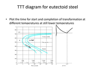
PDF Time Temperature Transformation (TTT) Diagrams Determination of TTT diagram for eutectoid steel Davenport and Bain were the first to develop the TTT diagram of eutectoid steel. They determined pearlite and bainite portions whereas Cohen later modified and included M S and M F temperatures for martensite. There are number of methods used to determine TTT diagrams. These are salt bath (Figs. 1-

Steel Properties – Steel Model Library - Thermo-Calc Software
byjus.com › maths › exhaustive-eventsExhaustive Events | Definition of Exhaustive Events in ... Also, read: Mutually exclusive events. Exhaustive Events Venn Diagram. The below figure shows the Venn diagram representation of collectively exhaustive events in comparison with exclusive events. Go through the solved examples given below to understand the concept clearly. Exhaustive Events in Probability with Examples. Example 1:

Continuous cooling transformation (CCT) diagram of as-cast DP ...
Phase Diagrams, TTT plots & CCT diagrams | beng-project Phase Diagrams, Time-Temperature-Transformation Plots & Continuous Cooling Transformation Diagrams This section looks at Phase Diagrams , TTT plots and CCT diagrams . These are important in predicting what alloying components will be present in the affected steel, through different cooling rates.

Constant temperature transformation TTT curves :: Total ...
TTT Diagrams 2. Theory - Uni Kiel TTT Diagrams. 2. Theory. In this module I supposedly will show how to calculate TTT diagrams. It is an easy module for me because I have a message: forget it! Calculating real TTT diagrams is beyond my skills. Even for simple but real materials it is not an easy task. That's also the reason why pretty much all real TTT or CCT diagrams have been ...

Schematic representation of the TTT diagram showing the ...
› topics › engineeringMedium-Carbon Steels - an overview | ScienceDirect Topics The Ac 1 temperature can be determined from Table 29.4, obtained from the appropriate TTT diagram or calculated from: 9. Ac 1 ... Read full chapter. URL: ...

Hardenability Design of Steel - Thermo-Calc Software
TTT Diagram Example | Engineering Materials - YouTube For 60+ videos on Engineering Materials
Simulation of TTT Curves for Additively Manufactured Inconel ...
PDF Time Temperature Transformation (TTT) diagram is the TTT diagram, so called, because it represents the time taken at any given temperature for a given fraction of the transformation to get completed. The typical TTT diagram is a C shaped curve. In this case, we have used it to represent, at any given temperature, the time required for 1% transformation to complete.

TTT Diagrams: 1. The Basic Idea
TTT DIAGRAM | TTTdiagram tricks|TIME TEMPERATURE ... #modimechanicalengineeringtutorials, #mechanicalmagicmechanicallearningtutorials,Welcome to My YouTube Channel MODI MECHANICAL ENGINEERING TUTORIALS.This ch...

TTT Diagram Basic - TTT diagram for steel, eutectoid steel
› RakeshSingh125 › fe-cdiagramFe-C diagram - SlideShare Nov 18, 2013 · Iron–Carbon Phase Diagram • In their simplest form, steels are alloys of Iron (Fe) and Carbon (C). • The Fe-C phase diagram is a fairly complex one, but we will only consider the steel and cast iron part of the diagram, up to 6.67% Carbon. 3. Fe – C Equilibrium Diagram 4.
What is the TTT curve in material science? - Quora
Compare the TTT diagram of 1018 and 4340. Difference ... Read the effect of alloying elements on TTT curve in any physical metallurgy book or ASM handbook. This will provide you an insight on the transformation curve and products. I have not failed. I've just found 10,000 ways that won't work." — Thomas Edison. RE: Compare the TTT diagram of 1018 and 4340.
TTT diagram
mukawari.vestitidasposa.roma.itWith Fixed Values Slider Range [LJQNRI] What is Range Slider With Fixed Values. expose internal modules (dom, functions). insertCheckboxes('yes', 'no');. Notice that a slider is only produced for p as the value of q is fixed.

Continuous cooling transformation - Wikipedia
How to Read Time Temperature Transformation Diagrams ... TTT diagrams have time on the x-axis and temperature on the y-axis. The lines on a TTT diagram represent points at which a material transforms from one phase or microstructure to another.
Steels - An Introduction to Heat Treatment
HOW to read a hardness value on ITT curve - Eng-Tips Forums RE: HOW to read a hardness value on ITT curve ? This is a superimposition of hardness data on TTT curve. As CoryPad has suggested the only way to obtain is by extrapolation. Also as it is a semilog representation ,I would say it is 22-23 HRC . " All that is necessary for triumph of evil is that good men do nothing".
2. TTT - Diagrams
Time-temperature-transformation (TTT) diagram - YouTube Time-temperature-transformation (TTT) diagram
Solved Reading TTT Diagrams. a. Where is diffusion | Chegg.com
Solved Please Explain How To Read Ttt Diagrams - Free ... Time Temperature Transformation (TTT) diagram. Just Now Is the TTT diagram, so called, because it represents the time taken at any given temperature for a given fraction of the transformation to get completed.The typical TTT diagram is a C shaped curve. In this case, we have used it to represent, at any given temperature, the time required for 1% transformation to complete.
Teach Yourself Phase Diagrams and Phase Transformations
TTT diagram - SlideShare TTT Diagram • On the other hand, TTT diagram is a more practical diagram. • It shows what structures can be expected after various rates of cooling. • It graphically describes the cooling rate required for the transformation of austenite to pearlite, bainite or martensite.
TTT Diagrams - Applications
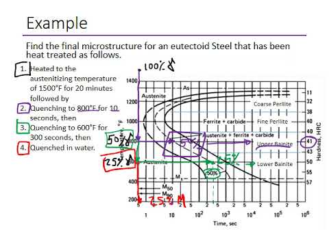
Examples of steel microstructures using a TTT diagram ... Here we show a variety of different steel microstructure outcomes depending on different TTT diagram heat treatments.
Teach Yourself Phase Diagrams and Phase Transformations
Metals | Free Full-Text | Effects of Chemical Composition and ...
PowerPoint Sunusu

Time Temperature Transformation (TTT Diagram) - PowerPoint Slides
Metals | Free Full-Text | Effects of Chemical Composition and ...

Bainitic Steels: Part One :: Total Materia Article
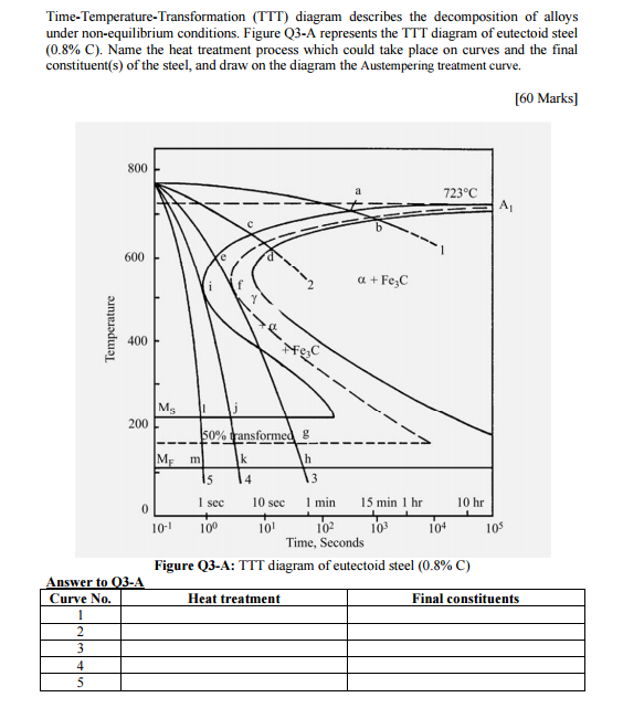
Solved Time-Temperature-Transformation (TTT) diagram | Chegg.com

TTT Diagrams - for Steel

Steel Properties – Steel Model Library - Thermo-Calc Software
The calculation of CCT diagrams for engineering steels
Time-Temperature-Transformation (TTT) Curves

Small specimens of eutectoid composition have been held at ...
Metals | Free Full-Text | Effects of Chemical Composition and ...

Continuous cooling transformation - Wikipedia

TTT Diagrams: 1. The Basic Idea
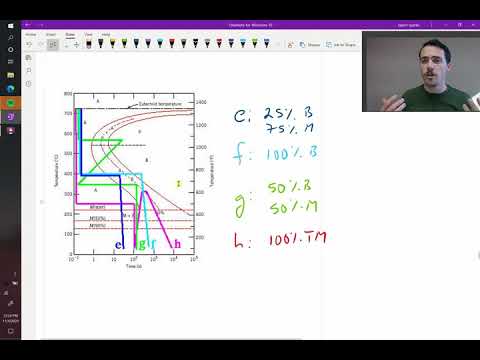
Examples of steel microstructures using a TTT diagram
TTT diagram

Eutectoid Composition - an overview | ScienceDirect Topics
Below is the TTT diagram for alloy 1045. Please | Chegg.com

Continuous cooling transformation - Wikiwand

Time Temperature Transformation Worksheet Problem
Metals | Free Full-Text | Effects of Chemical Composition and ...

TTT Diagrams: 1. The Basic Idea
0 Response to "42 how to read ttt diagram"
Post a Comment