41 pressure tank plumbing diagram
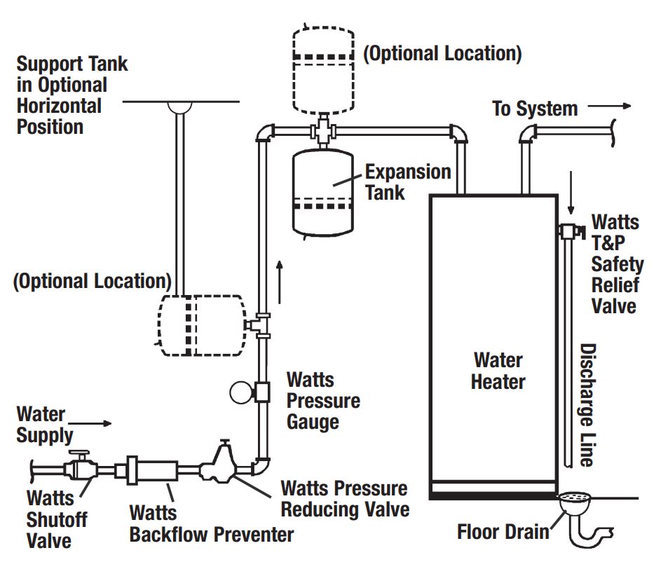
PDF Installation Manual DIAPHRAGM WELL TANK The tank pressure must be set 2 PSI lower than the pump cut-on pressure. Check tank pressure with a standard air gauge at the top of the tank as needed. ˆ$˘(2 ())'&(Where space is a critical factor, the in-line tank may be used or the <ˆ ˛ ˘ ˘ ˇ Various installations are shown. Also, to increase tank capacity up Plumbing Diagrams - Winnebago Plumbing Diagrams. Please choose a year from the menu at the left to start your search.
PDF Installation Manual DIAPHRAGM WELL TANK - Hot Water The pump tank has been shipped with a factory precharge as indicated on the tank label. If your pump start-up pressure is different from the factory precharge, adjust the tank pressure with the empty tank to your pump start-up pressure. This can be accomplished by simply bleeding air from valve in the top of the tank with an accurate pressure ...

Pressure tank plumbing diagram
PDF PLUMBING GUIDE - Ace Pumps PLUMBING DIAGRAM Anti-Vortex Tank Fitting Tank Valve Pressure Gauge Shut-off Valve Line Strainer Agitation Valve Agitation Pressure Gauge Jet Agitator Control Valve Flow Meter Boom Valves A = 10 x hose diameter A Pressure Spike Valve PLUMBING SUGGESTIONS PUMP MOUNTING The primary goal when plumbing a sprayer pump is to route liquid from the ... Plumbing Riser Diagram | Plumbing Services | New York Engineers Of course, the design of the building water distribution system will determine the layout of the plumbing riser diagram, whether or not waste water, and so in, is included in the diagram. Both the flow rate and the flow pressure are important criteria for water distribution systems and pipe sizes need to be selected in keeping with conditions ... How a Toilet Works & Toilet Plumbing Diagrams - HomeTips Sep 28, 2020 · How a Toilet Works – Toilet Plumbing Diagram. One of these devices—called a ballcock—is connected to the water supply and controls delivery of water to the tank. When the tank’s water rapidly drops down into the bowl (upon a flush), the pressure causes the bowl’s waste water to go down the drain.
Pressure tank plumbing diagram. Well Pressure Tank Installation | The Home Depot - YouTube This well pressure tank installation video shows the steps you'll need for this replacement. Be sure to follow the proper requirements listed below and in th... PDF Miles Van Camper Plumbing Diagram - Vanlife Outfitters grey inlet on top of tank vent line from top of tank 30 gallon grey water tank (underneath van) Note: this space between the grey tank and van body is actually only a few inches "tall" I have expanded the cavity shown in this illustration to make space for the two plumbing lines that connect to the top of the grey tank. In reality they are ... Piping size from pressure tank to softener and to house ... Plumbing and Piping - Piping size from pressure tank to softener and to house - I have a 1 line from my well to the pressure tank on one side of the tank tee. The tank is 44 gal with a 30/50 pressure switch and the bladder is set to 28 psi. I have a 1 line going back out to a frost free valve by the barn. I have it Pressure Tank - Clean Water Store List Price. Your Price. Qty. Stainless Steel Booster Pump 1.0 HP 220v 60hz Corrosion Proof. Select your Voltage Options: I need the standard 220v 60Hz I need 220v 50Hz Pump (for outside U.S.) P4000970. $800. $509.95.
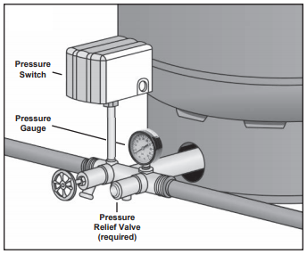
PDF Typical Submersible Pump Installation The air level in the tank should be 2 lbs. less than pressure switch turn-on level. For a 30-50 switch, this would be 28 lbs. of air with the tank dry. 2. Use a pressure switch featuring a low-pressure cut-out for wells of low or unknown production. 3. WARNING! A pressure relief valve is required by plumbing code and should be Well pump and water storage tank plumbing schematic (low ... Which is very similar to a diagram I drew a few years ago... When the "City Water" pressure is high enough, the pump doesn't switch on and the house gets "City" water at a good pressure. When the "City Water" pressure is low, the pump switches on and the house gets "tank" water at a good enough pressure. Well Pump & Pressure Tank Diagram - Well Water Report 7. Check Valve. Installed near the tank inlet to hold water in the tank during pump installation when the pump is idle. 8. Tank Tee. Connects water line from the pump to pressure tank and service line from tank to house. Taps are provided to accept Pressure Switch, Pressure Gauge, Drain Valve, Relief Valve, Sniffer Valve, etc. 9. Toilet Tank Parts: Plumbing Diagram, Pictures, Repairs ... Mar 05, 2020 · A toilet flapper is rubber seal at the bottom of the toilet tank that allows water to flow out of the tank to the bowl only during flushing but seals off the water movement the rest of the time. Its opening and closing is regulated by the toilet tank level with the help of a thin link chain.
Pressure regulator - Wikipedia A pressure regulator is a valve that controls the pressure of a fluid or gas to a desired value, using negative feedback from the controlled pressure. Regulators are used for gases and liquids, and can be an integral device with a pressure setting, a restrictor and a sensor all in the one body, or consist of a separate pressure sensor, controller and flow valve. Plumbing - Northwestern Tiny House Project | Pressure ... Steam Boilers Diagram, Are you search Steam Boilers Diagram pdf, word document or powerpoint text formats for free? ... Plumbing With PEX Tubing. ... A review of the best well pressure tank brands, how to size a pressure tank, and troubleshooting guide. Includes information on well water, off grid, Drink water, Shtf, Survivalist, Survivalism ... Well Pressure Tank Piping Layout - DoItYourself.com ... Cut the power to the pump and drain the tank completely. Your air pressure should be 2 psi below the cut in pressure, so if your pump kicks on at 20 psi, you want 18 psi air in the tank. Got that info here. How to Check the Bladder in a Well-X-Trol Tank | eHow.com. Mine looks to be the same size as yours. PDF Plumbing Systems of Agricultural Sprayers manual throttling valve to regulate major pressure changes while the electric regulating valve can be used to "fine tune" nozzle pressure from the operator's platform. Following are operational guidelines for using a spraying system with a centrifugal pump: Figure 2. Plumbing diagram for a centrifugal pump (nonpositive displacement pump).
RV Fresh Water System Diagram | Plumbing Schematic
DIY PRESSURE TANK INSTALL howto Plumb diaphram type Tank ... well Pressure Tank install DIY, A how to install a well pump pressure tank.diy plumbing, cheap, tips, and tricks. Replace a deep well pressure tank installed...

How a Well Pressure Tank Works - with Diagrams - Plumbing Sniper
Home Plumbing Diagram - Out of This World Plumbing Ottawa Your Home Plumbing Diagram This home plumbing diagram illustrates how your home should be plumbed. The different colour lines in this drawing represent the various plumbing pipes used. The blue lines are the fresh water supply entering the home. The red lines are the hot water supply after it has left the hot water tank.

Vertical Installation | Water Worker
Use a Pressure Tank to Combat Low Water Pressure ... Pressure tanks are more commonly used to complement well systems, but they can be a big help for homes on municipal lines as well. A pressure tank alone, integrated into your plumbing after the main shutoff valve, will keep the volume of water in your system high, maintaining pressure at a more constant level.

Water System Guide for DIY Camper Van Conversion - FarOutRide
Pentair Flotec FP7240 Air-Over-Water Pressure Tank ... Epoxy-lined standard water tanks are excellent corrosion resistant tanks for home water systems applications such as retention tank, holding tank and pressure tank. Key Features. Replaces any standard galvanized, glass-lined or epoxy-lined tank

Delton Marine
Need Help on Well Pressure Tank Layout | DIY Home ... 5,832 Posts. #5 · Feb 2, 2014. The simplest way to install the pressure tank is to purchase a well-T fitting, which is the fitting discussed by previous poster. This is typically a brass fitting that incorporates a port for the pressure gage, a drain, and a line to the pressure tank. See this website for full discussion of the theory and ...

PRESSURE TANK STYLES - HEDMAN DRILLING | PUMPS, INSPECTIONS ...
How a Well Pressure Tank Works - with Diagrams - Plumbing ... Water Pressure Tank Installation Diagram. The image below shows the typical installation diagram of a well pressure tank, as well as other components of a well system. Image: Lakeland Water Pump How a Bladder Pressure Tank Works. A bladder pressure tank is a steel tank with a bladder inside which looks like a balloon.

Well Pressure Tank Installation | The Home Depot
Diagrams --Typical Pump Installations Diagrams --Typical Pump Installations. The information provided here is for educational purposes only. Technically qualified personnel should install pumps and motors. We recommend that a licensed contractor install all new systems and replace existing pumps and motors. Failure to install in compliance with local and national codes and ...
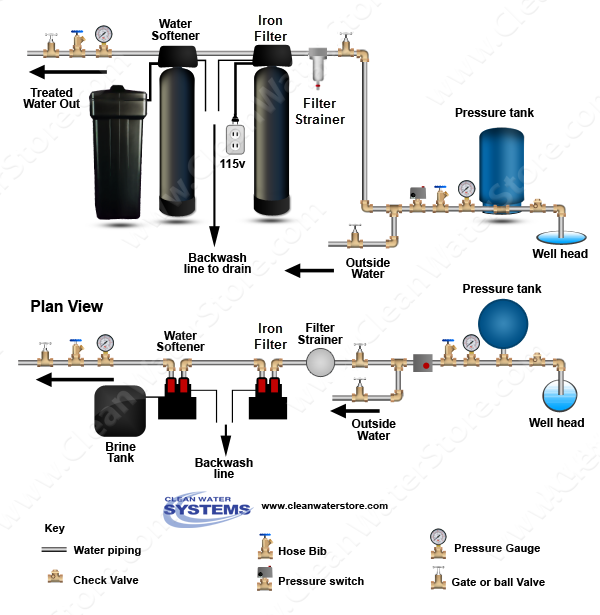
Where Should an Iron Filter Be Placed: Before or After the ...
PDF Pressure-Based Sprayer Plumbing Diagrams - Dultmeier output from this type of pump is influenced by pressure. This pump is ideal for delivering large volumes of liquid at low pressures. A key component of the centrifugal pump is the throttling valve. A manual throttling valve on the main output line is essential for the accurate operation of the centrifugal pump. Pressure-Based Sprayer Plumbing ...

Delton Marine
Flint and Walling Typical Piping Diagrams | Water well ... The WGB32B-PB whole house filtration system is an ideal "point of entry" filtration system for cleaning up well or city water. Unlike "point of use" systems (like reverse osmosis systems) that are installed to supply water to a specific faucet, the WGB32B-PB filters your water from the source.

Pressure tank, 5-hp pump, 2" galvanized drop pipe, and red ...
RV Fresh Water System Diagram | Plumbing Schematic Mar 17, 2020 · The high-pressure stream can help to dislodge any cemented fecal matter. Water Tank Monitors. There are two main types of tank monitors that you will commonly come across. Type One – Probe Sensors. This is the sensor type that is illustrated on the RV plumbing diagram.

A schematic of a typical plumbing connection to a private ...
Photo Guide to Well Water Pump Controls & Switches ... Water tank relief valves (red arrow in photo) were omitted by lots of plumbers installing pump, tank, and well systems, but most plumbing codes and local codes require a pressure relief valve on any tank which contains something under pressure, including a home water tank.

typ_2_wire.gif (593×528) | Submersible well pump, Well pump ...
Shower Parts Names: (Diagram & Explanation Of Plumbing Pieces) Feb 02, 2021 · The water pressure in your house determines the kind of shower you should install. For instance, a high-pressure system employing a combi boiler would fit well with a mixer shower. On the other hand, a low-pressure system is best with an electric shower. Additionally, this one also provides hot water immediately and consistently.

Bathroom Update! | Ana White
Parts of a Toilet - Toilet Tank Diagram - Best Home Gear Feb 26, 2022 · Toilet Tank Diagram . Tools Needed to Repair Toilet: In addition to studying the diagram and learning about all of the toilet parts, it is essential to fix a running toilet, you will need to grab the right tools to execute these simple repairs.
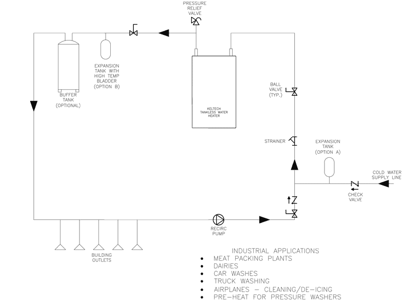
On-Demand Heater With Buffer Tank Plumbing Diagram - Bradley ...
RV Plumbing Diagram & Holding Tank Plumbing Diagram (2022) RV Holding Tank Plumbing Diagram 1. Fresh Water Tank. New water for your RV can be gotten in 2 distinct ways. In case you are snared to city water, it goes straightforwardly into the different lines inside your RV and feeds water straightforwardly.

Buy Plumb eeze Pressure Tank Installation Kit with 1 Brass ...
Well Pump & Pressure Tank Diagram - Clean Water Store Installed near the tank inlet to hold water in the tank during pump installation when the pump is idle. 8. Tank Tee Connets water line from pump to pressure tank and service line from tank to house. Taps are provided to accept Pressure Switch, Pressure Gauge, Drain Valve, Relief Valve, Sniffer Valve, etc. 9. Drain Valve Drain easy draining of ...
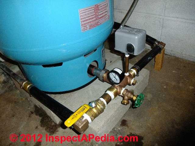
Photo Guide to Well Water Pump Controls & Switches - private ...
Pressure Washing Plumbing Diagram Follow along to learn how to properly set up your plumbing for your pressure washing trailer. ... Pressure Washing Plumbing Diagram. ... Buffer tank I recommend from the bottom. Or use a kit from Pressure Washer Products: 3-6.5 GPM Kit Leg Tank 3-6.5 GPM IBC Tote Kit. 8 GPM Kit Leg Tank 8 GPM IBC Tote Kit.
.png)
The Grey Nomads Forum
How a Toilet Works & Toilet Plumbing Diagrams - HomeTips Sep 28, 2020 · How a Toilet Works – Toilet Plumbing Diagram. One of these devices—called a ballcock—is connected to the water supply and controls delivery of water to the tank. When the tank’s water rapidly drops down into the bowl (upon a flush), the pressure causes the bowl’s waste water to go down the drain.

Improving Water Pressure - Fine Homebuilding
Plumbing Riser Diagram | Plumbing Services | New York Engineers Of course, the design of the building water distribution system will determine the layout of the plumbing riser diagram, whether or not waste water, and so in, is included in the diagram. Both the flow rate and the flow pressure are important criteria for water distribution systems and pipe sizes need to be selected in keeping with conditions ...

Technical Support Expansion vessels Flovarem | Expansion ...
PDF PLUMBING GUIDE - Ace Pumps PLUMBING DIAGRAM Anti-Vortex Tank Fitting Tank Valve Pressure Gauge Shut-off Valve Line Strainer Agitation Valve Agitation Pressure Gauge Jet Agitator Control Valve Flow Meter Boom Valves A = 10 x hose diameter A Pressure Spike Valve PLUMBING SUGGESTIONS PUMP MOUNTING The primary goal when plumbing a sprayer pump is to route liquid from the ...

How Does A Well Pump and Pressure Tank Work
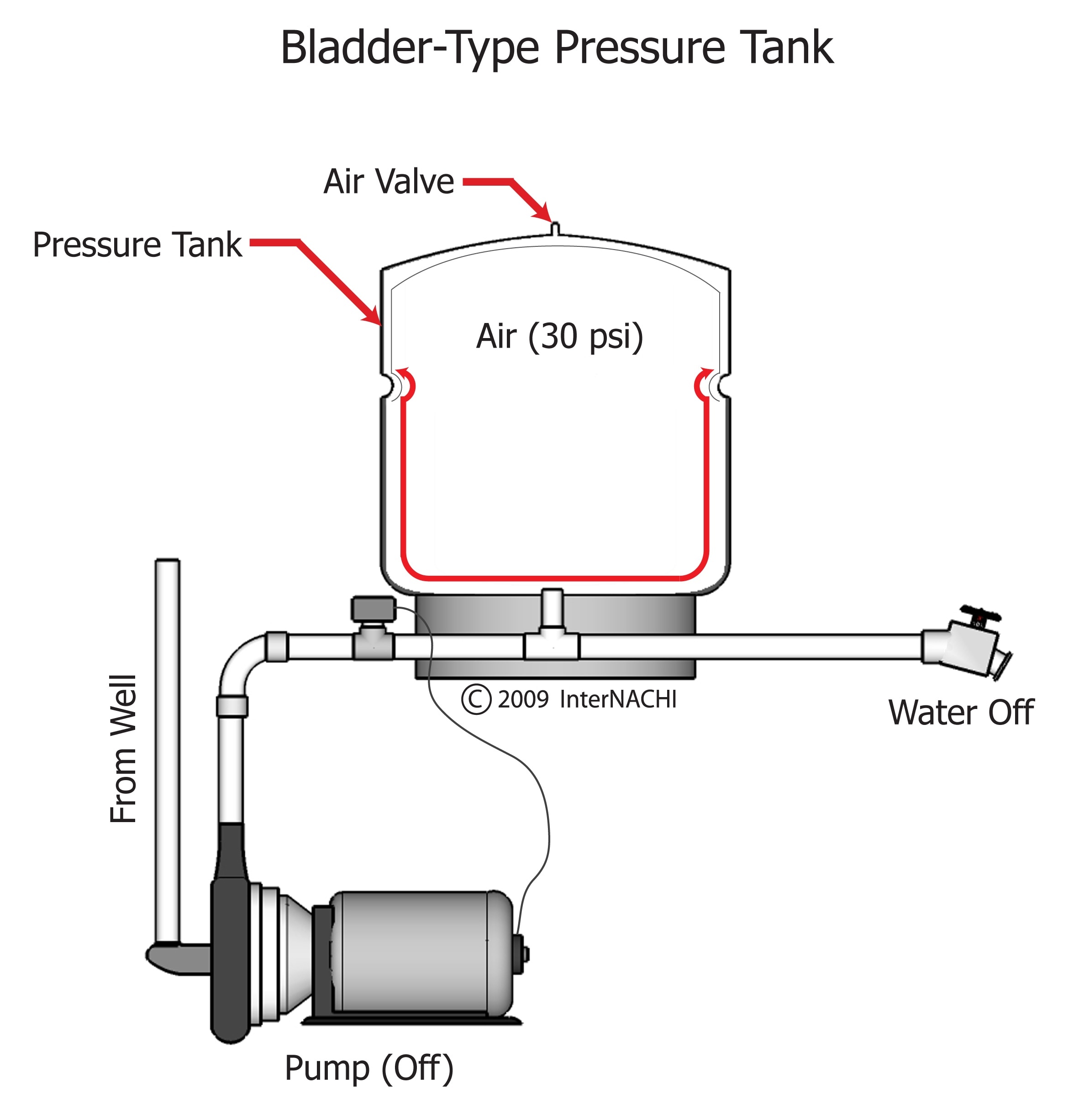
Bladder Type Pressure Tank - Inspection Gallery - InterNACHI®
How to Plumb an AODD Pump with Two Tanks and Transfer Chemical

Well and Water System Diagram - Apple River Well and Pump Company
RV Plumbing | Fresh Water Tank | Dump Tanks | Water Heater | Grey

Sizing a Pressure Tank - Your Step-by-Step Guide Dultmeier ...

Well Water Diagram |Calcite Neutralizer > Storage Tank ...

Plumbing - Northwestern Tiny House Project | Pressure tanks ...

Review my Sediment Filter Plan - Well Water - Filters Will Be ...
Domestic Service Water Supply Systems

Clean Well Water Report: Top 3 Ways to Automatically Turn On ...

water tank installation | Water storage, Storage tank, Water ...
Expansion tanks - Structure Tech Home Inspections

China 60L Vertical Pump Pressure Tanks for Water Supply ...

How to Install an Expansion Tank in Your Plumbing - Dengarden

Potable Water Expansion Vessels for Plumbing & Heating ...

Well Tanks & Pumps Davison & Lapeer, MI │ J.W. Bliss Plumbing
Well Pressure Tank Water Logged? | Home Well Water Tank Services

Desert Home: My Well, A Parody of Problems Part 5 (Discussion)

How Does A Shallow Well Pump Work With A Pressure Tank ...

Cleanwater Overview - Red Lion
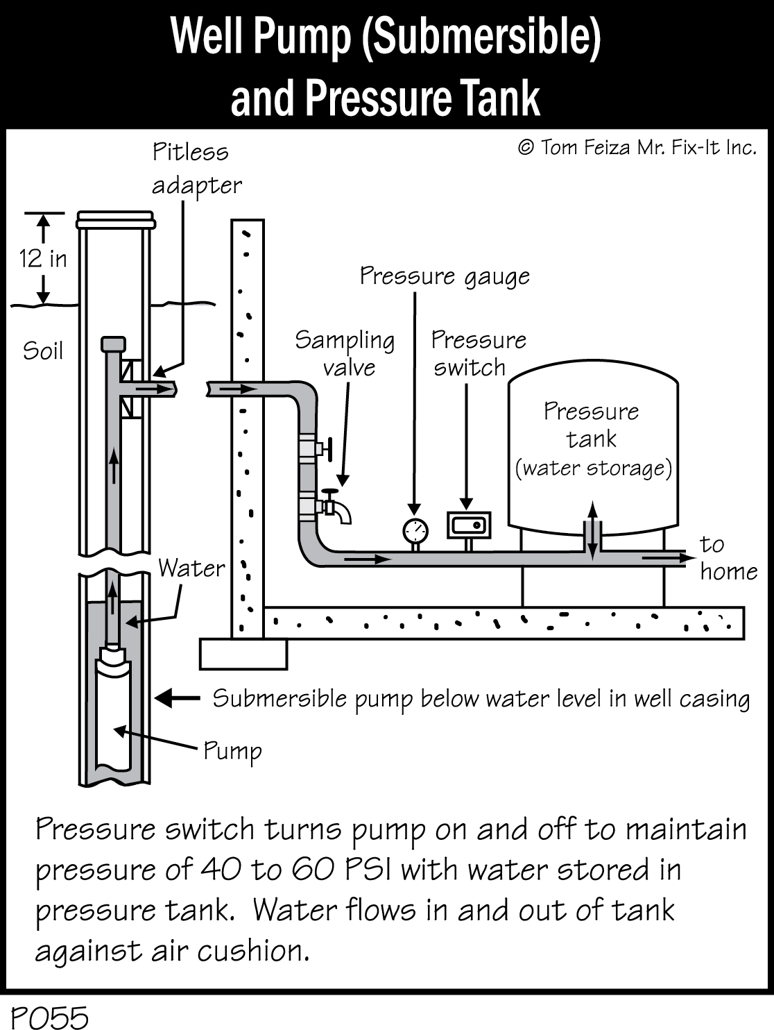
P055 - Well Pump and Pressure Tank, Submersible - Covered ...
0 Response to "41 pressure tank plumbing diagram"
Post a Comment