41 brake force brake controller wiring diagram
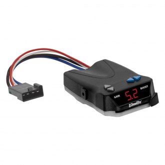
Brake Force Brake Controller Wiring Diagram - easywiring Wiring Diagram Brake Force Brake Controller Wiring Diagram by Vallery Masson on August 11, 2021 Auxiliary connection is optional it may be connected to any 12v to 24v constant power source or left unconnected. The brake forcetm came equipped with a quick connector plug wired to the back of the controller. Trailer Wiring and Brake Control Wiring For Towing Trailers Trailer Wiring and Brake Control Wiring. Tail Light Converters Brake Control Wiring Vehicles Towed Behind a Motorhome Wiring Diagram for Common Plugs Breakaway Switches. Special light and wiring systems need to be installed on your tow vehicle before you can tow any trailer.
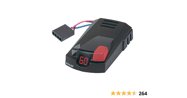
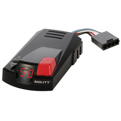
Hopkins 47225 Brake-Force Brake Controller Hopkins' Brake-Force trailer brake control combines simple installation with solid state dependability in a time-based, easy-to-use controller. ... Trailer Light Wiring T-Connectors Electric Brake Controllers 5th Wheel & Gooseneck Wiring 7 Pin Trailer Plug Wiring Connectors & Converters Mounting Brackets.
Brake force brake controller wiring diagram
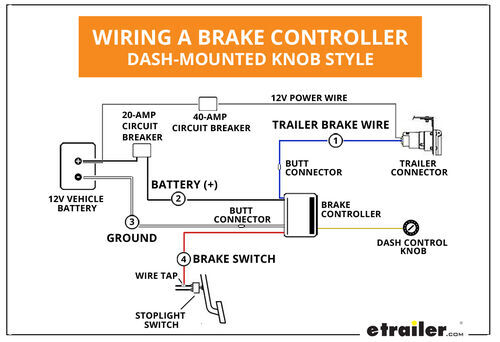
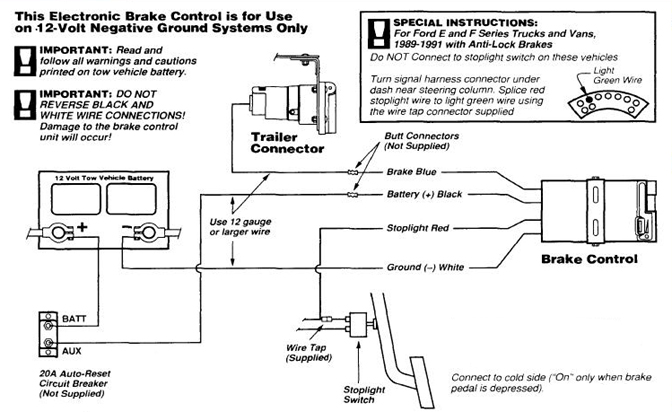
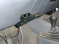
How To Install A Electric Trailer Brake Controller On A ... The wiring diagram to the right is a basic brake controller hook up. The wiring harness shown is typical of any electric brake control installation. Some newer vehicles provide their own brake control jumper harness which makes the install a plug and play affair. Brake-Force™ Brake Control - hopkinstowingsolutions.com The 47225 brake control utilizes time based actuation for applying braking power to the trailer brakes. An LED indicator will glow displaying braking intensity. The brighter the glow, the more braking force is being applied to the trailer brakes. Most states and provinces require a trailer brake controller based on the weight of the trailer. Hopkins Towing Solutions Brake-Force Electronic Trailer ... The Hopkins Towing Solutions Brake-Force Electronic Trailer Brake Control makes setting the right braking power easy. A multi-color LED display changes color to help guide you. The intuitive manual slide is designed to match the way a driver reaches for the control and activates the trailer brake lights. For use with trailers featuring systems ...
Brake force brake controller wiring diagram. Trailer Brake Controllers and Vehicle Wiring 7-Way Flat Pin Connector w/Brake Control Wiring #118799. Stock# 5223298. The 7-Way Flat Pin Pre-wired Brake Control Wiring Adapter allows you to quickly and easily wire your vehicle to accept a brake controller by utilizing your existing flat 4 connector. $72.50. PDF Installation Instructions The wiring installation utilizes the brake lights of the RV to activate the SMI system in combination with "G-Force." If the coach is equipped with an exhaust brake that illuminates the brake lights of the coach, extra attention must be given to the activation light. On steep grades all G-Force sensors will sense inertia faster and more quickly Brake Controller Installation: Starting from Scratch ... I have a 16 ft jayco starcraft caravan with electric brakes.I have fitted a tekonsha primus iq brake controller to my tow vehicle.The controller is showing that there is a short in the wiring.On unplugging brake magnets the wiring is clear.Each magnet is measuring 3.4 ohms and testing from the tow plug the measurement is 1.7 ohm.The brakes are ... PDF Brake-force Universal Installation on the trailer will damage the brake control. • This brake control is designed to operate with electric trailer brakes and not electric-hydraulic brake systems. WIRING GUIDE: The BRAKE-FORCETM came equipped with a quick connector plug wired to the back of the controller. OPTION: If your vehicle came equipped with a factory tow package, brake ...
PDF Pacbrake Brake Controller Troubleshooting wiring. If exhaust brake DOES NOT still activate immediately: Controller thinks parameters are right for activation. Check that this is the case (warm-up feature, etc). If all has been checked and brake is confirmed that it should not be on in this scenario, likely a sensor failure on the truck relating to a required input parameter for brake ... Brake Force Brake Force specializes in brakes, vehicle maintenance, and full service auto repair! Our expert certified mechanics and technicians are ready to perform any repair or service you may need to help ensure your family is back safely on the road as quick as possible! Brake Force is Family owned and locally operated. PDF Impulse Brake Controller Wiring Diagram Read PDF Impulse Brake Controller Wiring Diagram Impulse Brake Controller Wiring Diagram This is likewise one of the factors by obtaining the soft documents of this impulse brake controller wiring diagram by online. You might not require more time to spend to go to the books start as without difficulty as search for them. PDF Wiring Instructions For Electronic Brake Controls Wiring Instructions For Electronic Brake Controls P/N 4399 REV K Generic Wiring Diagram READ THIS FIRST: Read and follow all instructions carefully before wiring brake control. Keep these instructions with the brake control for future reference. Important Facts to Remember 1. The brake control must be installed with a 12 volt negative ground ...
PDF 47225-instr. sheet - Northern Tool IMPORTANT NOTES ABOUT YOUR HOPPY® BRAKE CONTROL The green light draws only 10 milliamps and will take 6 months to drain a charged vehicle battery. Works only with a 12-volt system. Brake lights on the vehicle and trailer activate when the manual slide is pushed. Unit is short-proof protected from electric trailer brake wiring shorts. Ford Trailer Brake Controller Wiring Diagram - Wirings Diagram There are two things that will be present in any Ford Trailer Brake Controller Wiring Diagram. The first component is symbol that indicate electric element from the circuit. A circuit is generally composed by several components. Another thing which you will discover a circuit diagram would be traces. Electric Brake Controller Wiring Diagram : Elecbrakes Electric Brake Controller Wiring Diagram. Wiring Diagram. Auxiliary connection is optional, it may be connected to any 12v to 24v constant power source or left unconnected. Break away systems may be added to the service brake circuit. Elecbrakes is designed to operate 1 to 2 braked axles. Get. 8 Best Brake Controllers for Trailers - 2022 - Hitch Review Wiring a brake controller during installation typically involves 4 wires: ... Mainly found on Draw-Tite Brake Controllers, it determines the amount of stopping force the brake controller puts out. If you set the sync power low, it does not matter how hard you hit the brakes, as they will be applied lightly. ...
Amazon.com: Hopkins 47235 Impulse Plug-in Simple Brake ...
PDF Air Force One - Ultra RV Products spring-brake valve and insert the tee with the 3/8" close nipple between them. Remove the two lines going from the spring-brake valve to the air cans on either side of the drive axle. Caution - It is possible for the spring-brake/quick release valve to un-thread incorrectly resulting in disassembly of the valve. It is safest to

How To Install An Electronic Trailer Brake Controller
Brake Controllers - Draw-Tite Draw-Tite Activator Electronic Brake Control 1-2 Axle Trailers (2-4 Brake Trailers) $79.00 Activator® IV Electronic Brake Control, for 1 to 4 Axle Trailers, Timed Actuated

Vehicle Stability Control with Regenerative Braking and ...
Installing Hopins Brake Force Brake Controller on 2010 ... Installing Hopins Brake Force Brake Controller on 2010 Toyota Tundra. Question: ... you will have to hardwire the controller into the existing vehicle wiring. We offer a Brake Controller Installation Kit, part # ETBC7 for a 7-way connector or part # ETBC6. We have a brake controller install guide that you might find helpful, I will include a ...
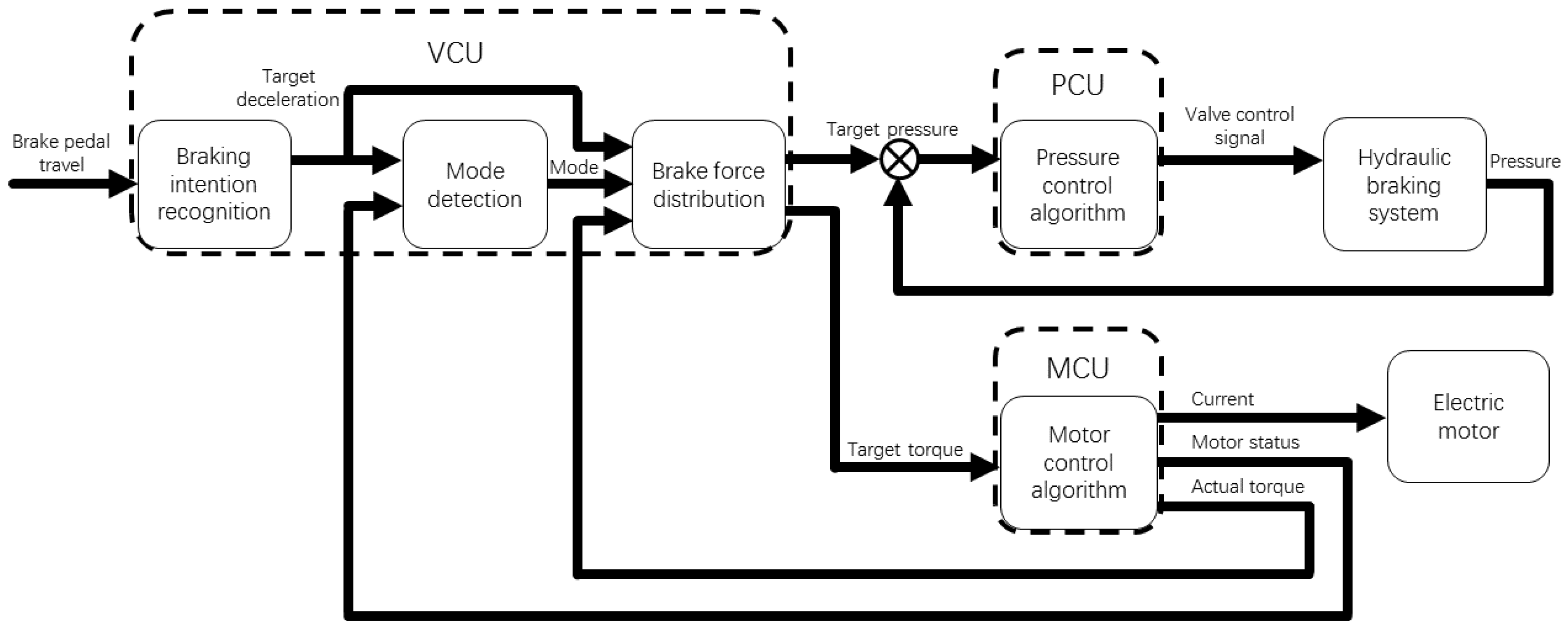
Energies | Free Full-Text | Development of a Cooperative ...
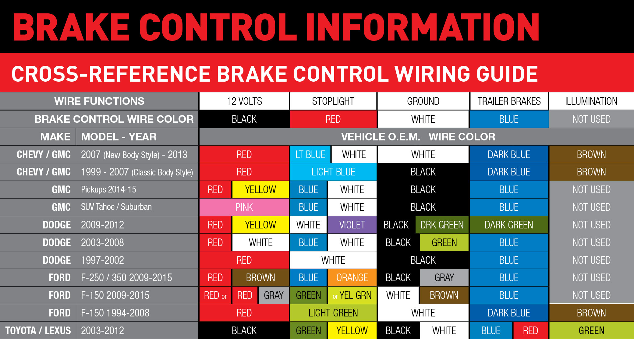
Brake Force Electric Brake Controller Wiring Diagram ... Brake force electric brake controller wiring diagram. The black wire is the power supply line to the brake control. Wiring instructions for electronic brake controls p n 4399 rev k generic wiring diagram read this first. Auxiliary connection is optional it may be connected to any 12v to 24v constant power source or left unconnected.
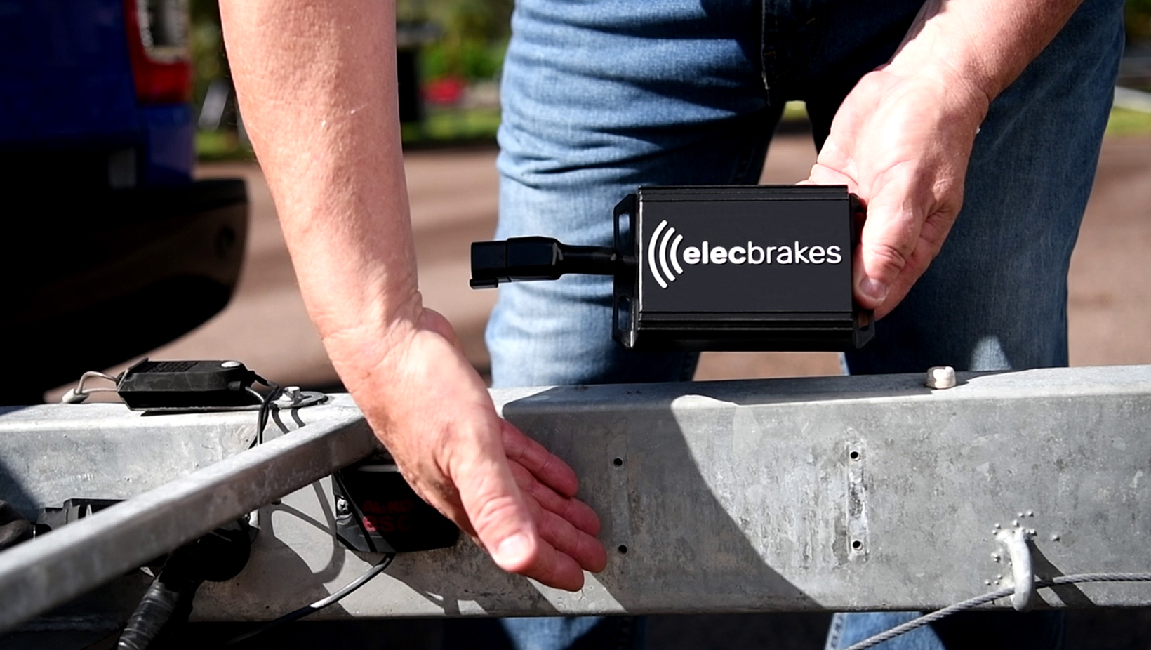
How Does An Electric Brake Controller Work? | Elecbrakes
How to Use a Trailer Brake Controller - Towing 101 Using a brake controller while towing a trailer involves setting up the controller, adjusting to the load size, adjusting braking sensitivity, manually activating the trailer brakes and possibly choosing a few personal settings. In this guide we will unpack how a trailer brake controller works and the steps involved in how to use a brake controller while towing with trailer brakes.

How To Install An Electronic Trailer Brake Controller
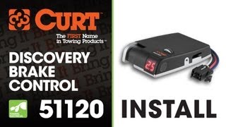
PDF DISCOVERY BRAKE CONTROL INSTALLATION AND USER GUIDE For ... Run a 10 gauge blue wire from the tow vehicle's trailer plug 'brake' terminal to the brake control. Using a 10/12 butt connector, connect this wire to the brake control's blue wire. Connect the brake control's red wire to the cold side of the tow vehicle's stoplight switch using a wire tap.
Towing a Trailer? Let's Talk About Brake Controllers ...
PDF Installation Instructions - Ultra RV Products adjust the G-Force Controller II accordingly. The SMI Stay-IN-Play Duo's brake actuator uses an internal spring to retract the brake pedal, thereby assuring there is no drag on the towed vehicle's brakes. Be-fore towing, check the operation of the air cylinder with the breakaway and observe the operation of the brake pedal.
Trailer Brake Controllers | Proportional, Time Based, Wiring
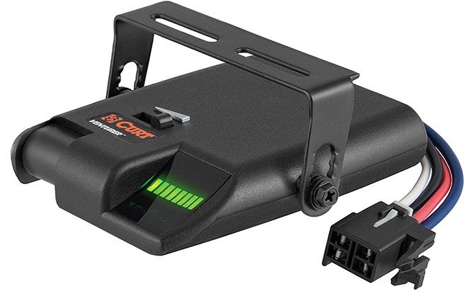
Hopkins 47225 Brake Force Plug-in Simple Brake Control Plug-in simple connection allows for quick installation and removal without cutting or splicing. Time based with a LED indicator that shows braking intensity. Intuitive, vertical manual slide matches the way a driver reaches for the control. Short proof protected with a 4 brake capacity. Can be mounted at any angle.
Trailer Brake Controller Installation How-To - 5 Easy Steps!
PDF Brake Control Wiring Diagram - AnythingTruck.com The brake control must be installed with a 12 volt negative ground system. (To install with a positive ground system use Tekonsha ® P/N 3191.) 2. WARNING Reversing BLACK and WHITE wires or improper wiring will damage or destroy brake control. 3. WARNING Be sure to solidly connect all four wires or brake control will not function properly. 4.
Trailer Brake Control Wiring Diagram
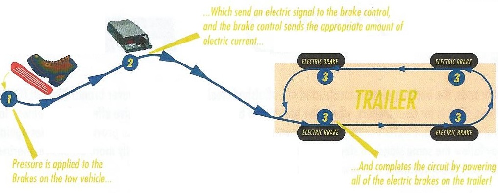
PDF Electric Brakes - Forest River Braking System Diagram (Fig. 1) and the brake diagram table below to follow along.) 1. Electric current is supplied to the coach braking system when the tow vehicle's brakes are applied. 2. From the tow vehicle's battery, the electricity flows to the coach brake magnet. 3.

Hopkins Towing Solutions Impulse Brake Control | 9185526 ...
Hopkins Towing Solutions Brake-Force Electronic Trailer ... The Hopkins Towing Solutions Brake-Force Electronic Trailer Brake Control makes setting the right braking power easy. A multi-color LED display changes color to help guide you. The intuitive manual slide is designed to match the way a driver reaches for the control and activates the trailer brake lights. For use with trailers featuring systems ...

53056 Hopkins MFG Trailer Brake System Connector/ Harness Compatible With Hopkins/ Agility/ Insight/ Reliance Or Brake Force Controller
Brake-Force™ Brake Control - hopkinstowingsolutions.com The 47225 brake control utilizes time based actuation for applying braking power to the trailer brakes. An LED indicator will glow displaying braking intensity. The brighter the glow, the more braking force is being applied to the trailer brakes. Most states and provinces require a trailer brake controller based on the weight of the trailer.
The Best Trailer Brake Controllers and Why You Need One, 2022 ...
How To Install A Electric Trailer Brake Controller On A ... The wiring diagram to the right is a basic brake controller hook up. The wiring harness shown is typical of any electric brake control installation. Some newer vehicles provide their own brake control jumper harness which makes the install a plug and play affair.
Trailer Brake Control | Auto Value
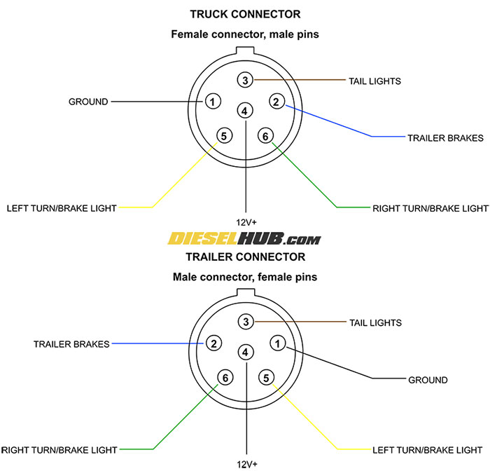
Trailer Connector Pinout Diagrams - 4, 6, & 7 Pin Connectors
Brake Controller Installation: Starting from Scratch ...

Show & Tell: AC Reversible Motors and AC Electromagnetic ...
BRAKERITE ELECTRIC HYRAULIC BRAKE ACTUATION SYSTEMS ...

Tow-Pro Liberty Electric Brake Controller – REDARC

The EASIEST Way to Install A Brake Controller!
BRAKERITE ELECTRIC HYRAULIC BRAKE ACTUATION SYSTEMS ...

Brake Hand Controller Hopkins The Brake-Force 47225
Hopkins Agility Trailer Brake Controller - Plug In - 1 To 4 ...
Wiring Guides

Hopkins Towing Solution 47635 Trailer Brake Control Quick ...

How To Install An Electronic Trailer Brake Controller

9107A Electric Brake Force Meter | Innovative Products of America

Wiring diagram for brake controllers | Trailer Spares Direct ...

Redarc Tow-Pro Elite Brake Controller

Tuson Sway Control (TSC-1000) – Tuson RV Brakes, LLC

Tow-Pro Liberty Electric Brake Controller

Redarc Tow-Pro Elite Brake Controller
How Electric Brakes Work
NEO TRAILERS - MANUAL
Electric friction brake - Wikipedia

Redarc Tow-Pro Elite Brake Controller

The Best Trailer Brake Controllers and Why You Need One, 2022 ...
Razor Ground Force Electric Go Kart Parts ...

Replace Skid Control Ecu Dtc C Booster Pedal Force Switch ...
Caravan Electric Brakes - How to test trailer brake magnet wiring

How To Install An Electronic Trailer Brake Controller
0 Response to "41 brake force brake controller wiring diagram"
Post a Comment