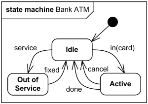
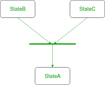
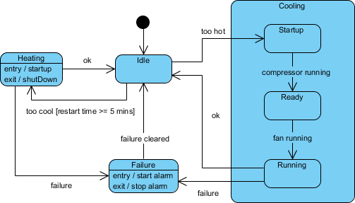
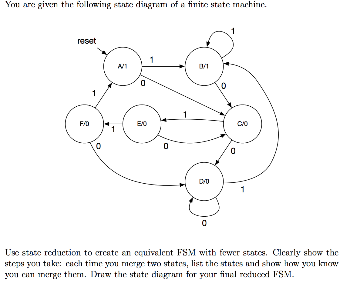
39 in a state machine diagram, a state is represented by a(n) _______.
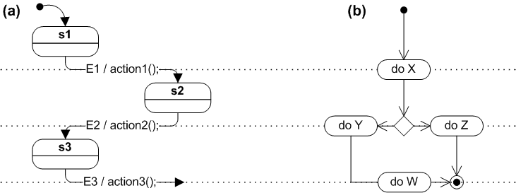
UML State Machine Diagrams - Overview of Graphical Notation State machine diagram is a behavior diagram which shows discrete behavior of a part of designed system through finite state transitions. State in behavioral state machines models a situation during which some (usually implicit) invariant condition holds. The invariant may represent a static situation... ch 5 Flashcards | Quizlet In a state machine diagram, a state is represented by a(n) ____. On a sequence diagram when multiple messages are included within a repeating loop a(n) _ is used to document it.
› finite-state-machineFinite-State Machine - an overview | ScienceDirect Topics A finite state machine (FSM) [71] is a mathematical model of computation usually represented as a graph, with a finite number of nodes describing the possible states of the system, and a finite number of arcs representing the transitions that do or do not change the state, respectively. Such a machine is mostly used to model computer programs ...

In a state machine diagram, a state is represented by a(n) _______.
Composite State shape Create a UML state machine diagram. In a statechart diagram, a composite state is a state that has been decomposed into concurrent (representing "and" Mutually exclusive states (supported in the UML Model Diagram ) are represented by a nested state diagram within an enclosing state. creately.com › blog › diagramsUML Diagram Types | Learn About All 14 Types of UML Diagrams Sep 10, 2021 · Get More State Chart Diagram Examples >> Sequence Diagram. Sequence diagrams in UML show how objects interact with each other and the order those interactions occur. It’s important to note that they show the interactions for a particular scenario. The processes are represented vertically and interactions are shown as arrows. A simple guide to drawing your first state diagram — with... | Cacoo A state diagram is a graphic representation of a state machine. It shows a behavioral model consisting of states, transitions, and actions, as well as This is when a moment triggers a shift. These are represented by labeled transition arrows. In the example above, pressing CapsLock is the event...
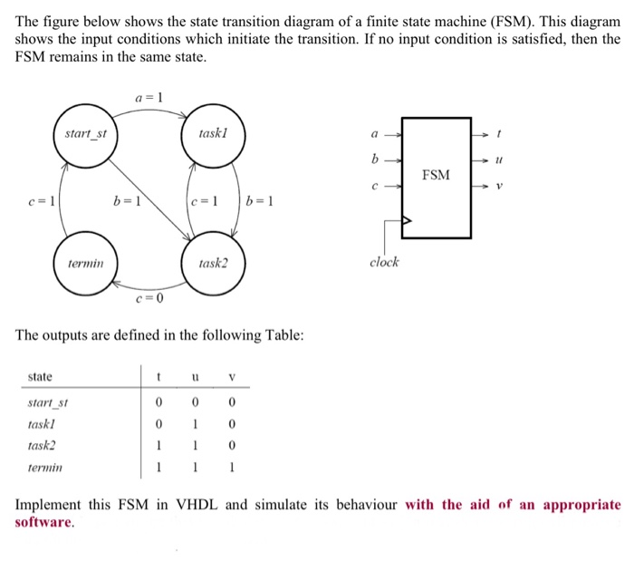
In a state machine diagram, a state is represented by a(n) _______.. what is a state transition or state machine diagram?how to make it UML 2 State Machine Diagrams. Derek Banas. State Machine Diagram in OOAD by Sandeep Kumar. UML State Machine Diagram - Training Material State machine diagram is a behavior diagram which shows discrete behavior of a part of designed system through finite state transitions. State machine diagrams can also be used to express the valid interaction sequences (protocols) for parts of a system. PDF CHAP5.dvi | State-Space Representation of LTI Systems The so-called state-space description provide the dynamics as a set of coupled rst-order dierential equations in a set of internal variables known as state variables, together with a set of algebraic equations that combine the state variables into The block diagram representation is shown in Fig. › technical-articlesImplementing a Finite State Machine in VHDL - Technical Articles Dec 23, 2015 · For example, in this system, the state machine moves from state A to state B if the input P is equal to 1 (otherwise it remains in state A) The information underneath the line in the circle represents the output value when in each state. The arrow coming from "nowhere" to the A indicates that A is the initial state. Figure 1. A Simple Finite ...
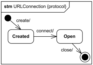
How to Implement State Machines in Your FPGA A state diagram shows the states, the transitions between states and the outputs from the state machine. Figure 1 shows two state diagrams Some engineers feel that a state machine described in ASM format is easier to map to implementation in a hardware description language such as VHDL. State diagram - Wikipedia (Redirected from State machine diagram). A state diagram is a type of diagram used in computer science and related fields to describe the behavior of systems. State diagrams require that the system described is composed of a finite number of states; sometimes, this is indeed the case... Welcome to Real Digital | State Diagram A state diagram represents states with circles, and transitions between states by arrows exiting one circle and arriving at another. A binary number called the state code can be written in the state-circle to indicate the value stored in the state register when the state machine is in that state. Unified Modeling Language (UML) | State Diagrams - GeeksforGeeks The state diagram above shows the different states in which the verification sub-system or class exist for a particular system. Figure - a state with internal activities. Final state - We use a filled circle within a circle notation to represent the final state in a state machine diagram.
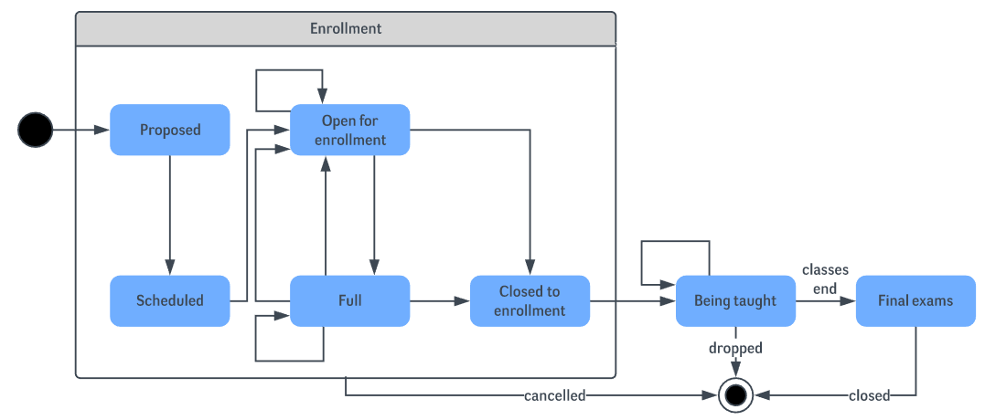
Guidelines: Statechart Diagram | History States A statechart diagram shows a state machine, which specifies the sequences of states that an object can be in, the events and conditions which cause the object to reach A final state is represented as a filled black circle surrounded by an unfilled circle. Initial and final states are really pseudostates. UML State Machine Diagram Tutorial: Explain with Examples A UML State machine diagram is basically open for any type of shape and elements. However, there are also symbols that you will commonly encounter here and most It is represented by a black circle with an arrow attached to it. State - States are the main star of this type of diagram, hence its name. Encoding the States of a Finite State Machine in VHDL - Technical... The State Diagram Representation of an FSM. We can use a state diagram to represent the operation of a finite state machine (FSM). For example, consider the state diagram shown in Figure 1. This FSM has eight states: idle, r1, r2, r3, r4, c, p1, and p2. Implementing a State Machine in C++17 - blogersii Finite State Machines are a very useful concept that allows modeling complex behavior. The basic idea is quite simple. We have a set of possible states and we define rules that govern transitions between the Let's see how it all works together by implementing a simple state machine representing a door.
UML State Diagram: A Useful Guide - Edraw A UML state diagram also referred to as a state machine, holds information of an object with It is the current physical situation of an object. A rounded edge rectangle usually represents it The focus with this state diagram here is to look into the developments taking place in an authentication process.
UML 2 State Machine Diagrams: An Agile Introduction UML state machine diagrams depict the various states that an object may be in and the transitions between those states. In fact, in other modeling languages, it is An object starts in an initial state, represented by the closed circle, and can end up in a final state, represented by the bordered circle.
› courses › archiveExample finite state machine - Princeton University In this diagram, the bubbles represent the states, and the arrows represent state transitions. The arrow labels indicate the input value corresponding to the transition. For instance, when the elevator is in the Ground state, and the input is Up, the next state is First.
SysML FAQ: What is a State Machine diagram (SMD)? State: A State (notation: rounded-rectangle a.k.a. "roundangle") represents a condition or situation during the life of an object during which it satisfies some condition, performs some When properly applied (See Usage Notes below) State Machine diagrams are recursively scalable and simulatable.
en.wikipedia.org › wiki › Finite-state_machineFinite-state machine - Wikipedia The turnstile state machine can also be represented by a directed graph called a state diagram (above). Each state is represented by a node (circle). Edges (arrows) show the transitions from one state to another. Each arrow is labeled with the input that triggers that transition.
stackoverflow.com › questions › 5923767Simple state machine example in C#? - Stack Overflow May 08, 2011 · There is the third alternative; really drawing the state machine. If you are using .NET and can target version 4 of the run time then you have the option of using workflow's state machine activities. These in essence let you draw the state machine (much as in Juliet's diagram) and have the WF run-time execute it for you.
uml - State Machine Diagram - Two States for same... - Stack Overflow State machine basics. In your SM , there is no region, no composite state, nor submachines. There can therefore only be at most one state active at a given A particular execution of a StateMachine is represented by a set of valid path traversals through one or more Region graphs, triggered by the...
PDF State Machines | 3.3.1 State transition diagram Specically, a state machine StateMachine is a 5-tuple, StateMachine = (States, Inputs, Outputs, update, initialState). In this bubbles-and-arcs syntax each bubble represents one state of the answering machine, and each arc represents a transition from one state to another.
UML State Machine Diagram: Structure and Application - IONOS The UML state machine diagram can be used to map object states and help to better understand them. But how do you create a state machine diagram? States are the central components of a state machine diagram. All real states are always represented with a rectangle with rounded corners.
State Machine Diagram Tutorial | Lucidchart State diagrams mainly depict states and transitions. States are represented with rectangles with rounded corners that are labeled with the name The point at which an object escapes the composite state or state machine, denoted by a circle with an X through it. The exit point is typically used if the...
brilliant.org › wiki › finite-state-machinesFinite State Machines | Brilliant Math & Science Wiki Finite state machines can be used to model problems in many fields including mathematics, artificial intelligence, games, and linguistics. A system where particular inputs cause particular changes in state can be represented using finite state machines. This example describes the various states of a turnstile.
State Machine Diagram - an overview | ScienceDirect Topics The diagram kind for a state machine diagram is stm , and the model element kind is always stateMachine . Because of this, the model element kind in square brackets is • Any other action in the transition effect is represented by a rectangle containing text that describes the action to be taken.
The State Design Pattern vs. State Machine - CodeProject Also, I have seen state machines being used instead of state design patterns at the costs of horribly I will discuss the state design pattern on how it can be used in a fairly complex scenario and demonstrating The context is an object that represents a thing that can have more than one state.
PDF State Machines | Building Statechart Diagrams • Composite States can be further broken down into substates (either within the state or in a separate diagram). • A composite state is a state with one Behavioural state machines show the behavior of model elements such as objects. A behavioural state machine represents a specic implementation...
What is State Machine Diagram? The initial state of a state machine diagram, known as an initial pseudo-state, is indicated with a solid circle. A transition from this state will show the An open loop state machine represents an object that may terminate before the system terminates, while a closed loop state machine diagram does...
State Machine diagram - MagicDraw 18.4 - Documentation State Machine diagrams (also called Statechart diagrams) represent the behavior of entities capable of dynamic behavior by specifying its response to the A change of a State is called a Transition. A Transition may also have an action connected to it that specifies what should be done in connection...
Problem Solving: Finite state machines - Wikibooks, open books for... A finite state machine consists of states, inputs and outputs. The number of states is fixed; when an input is executed, the state is changed and an output is possibly produced. Finite state machines are widely used when designing computer programs, but also have their uses in engineering, biology...
What is State Machine? - Definition from Techopedia State machines are represented using state diagrams. The output of a state machine is a function of the input and the current state. The operation of a state machine begins from a start state. On a successful transition it ends up in an accept state. The transition takes place based on the inputs...
A simple guide to drawing your first state diagram — with... | Cacoo A state diagram is a graphic representation of a state machine. It shows a behavioral model consisting of states, transitions, and actions, as well as This is when a moment triggers a shift. These are represented by labeled transition arrows. In the example above, pressing CapsLock is the event...
creately.com › blog › diagramsUML Diagram Types | Learn About All 14 Types of UML Diagrams Sep 10, 2021 · Get More State Chart Diagram Examples >> Sequence Diagram. Sequence diagrams in UML show how objects interact with each other and the order those interactions occur. It’s important to note that they show the interactions for a particular scenario. The processes are represented vertically and interactions are shown as arrows.
Composite State shape Create a UML state machine diagram. In a statechart diagram, a composite state is a state that has been decomposed into concurrent (representing "and" Mutually exclusive states (supported in the UML Model Diagram ) are represented by a nested state diagram within an enclosing state.
















0 Response to "39 in a state machine diagram, a state is represented by a(n) _______."
Post a Comment