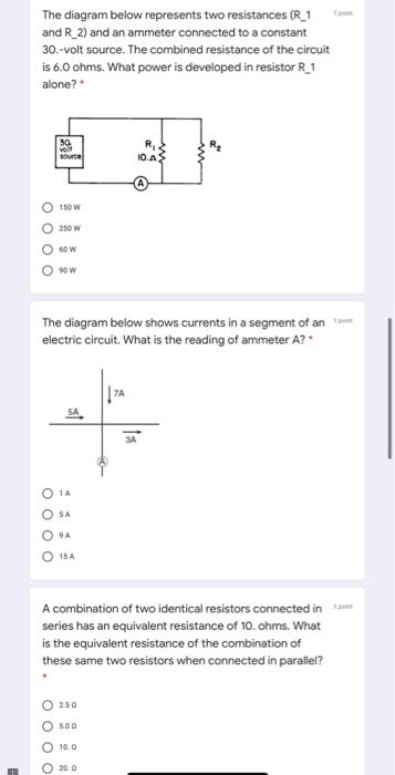
39 the diagram below shows currents in a segment of an electric circuit
electric circuit | Diagrams & Examples | Britannica Electric circuit, path for transmitting electric current. In a home electrical circuit, for instance, the same voltage is applied across each light or appliance, but each of these loads draws a different amount Diagram showing a voltmeter connected to a simple circuit. Encyclopædia Britannica, Inc. Series RLC Circuit and RLC Series Circuit Analysis Electrical Tutorial about the Series RLC Circuit and Electrical Analysis of a Series RLC Circuit The resulting angle obtained between VS and i will be the circuits phase angle as shown below. As we have taken the current vector as our reference vector in a series RLC circuit, then the current "lags"...
Electric CIrcuits simulation (Phet). Electric circuits simulation activity. Electric circuits simulation with activity for students to discover the rules for current and PD in electric circuits . A series circuit is one in which all the components come one after the other in a single loop. Now right click on the battery and change the voltage to the amounts shown in the table below.
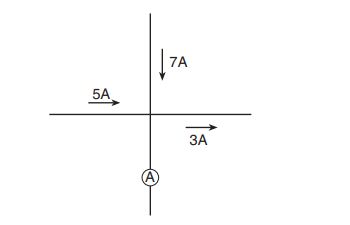
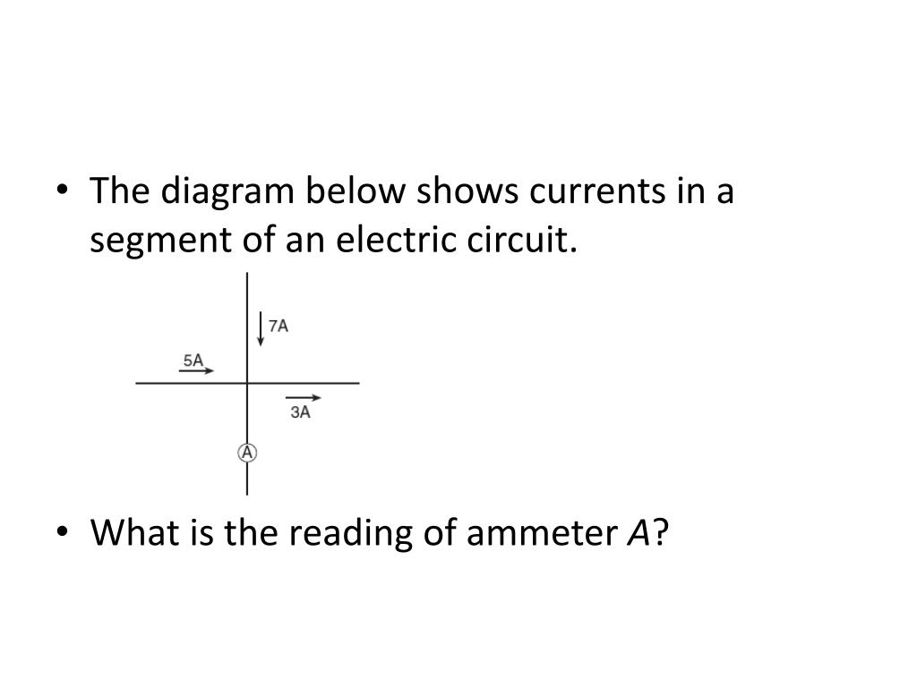
The diagram below shows currents in a segment of an electric circuit
What is an Electrical Circuit? - Codrey Electronics | Circuit Diagram Electrical circuit is an interconnection of electrical components. A circuit is a closed path where electrons flow in a wire. As long as the copper wire is allowed to itself, the electrons drift between the atoms but never leave the copper. Classwork/HW Name: Date: 1. Base your answer(s) to the ... 25 Mar 2019 — [Show all work, including the equation and substitution with units.] 48. The diagram below shows currents in a segment of an electric circuit.10 pages circuitdigest.com › electronic-circuits › clapClap Switch Circuit Diagram using IC 555 Jun 05, 2015 · Clap switch is an interesting hobby circuit which turns on the lights with a clap sound. Although its name is “Clap switch”, but it can be turned ON by any sound of approximately same pitch of Clap sound. The main component of this clap switch circuit is the Electric Condenser Mic, which has been used as a sound sensor. Condenser Mic ...
The diagram below shows currents in a segment of an electric circuit. In the circuit of the figure below determine the current - YouTube In the circuit of the figure, determine (a) the current in each resistor and (b) the potential difference across the 200-Ω resistor. PDF Chapter 2: Circuit Elements | Mesh Current Method Algorithm Figure 4.1 (left) shows a circuit that has crossing branches but that can be re-drawn without any branches crossing. The number of nodes in a circuit is n. A path is formed when adjoining (connected) circuit elements are traced, in order, without passing through any node more than once. PDF Unit 43: Current, voltage and resistance Dr. Basil Hamed Technical... The circuit diagrams below show lamps connected in a parallel circuit and in a series circuit. The supply has live and neutral conductors. A short circuit is when current flows directly from a live conductor to a neutral conductor -for example, due to damaged insulation. PDF Fundamentals of Electric Circuits (5th ed) Fundamentals of electric circuits, fifth edition. Published by McGraw-Hill, a business unit of The McGraw-Hill Companies, Inc., 1221 Avenue of the Americas, New York, NY 10020. RLC Circuit 319 8.4 The Source-Free Parallel. RLC Circuit 326 8.5 Step Response of a Series RLC.
Physics Tutorial: Circuit Symbols and Circuit Diagrams Electric Circuits - Lesson 4 - Circuit Connections. Circuit Symbols and Circuit Diagrams. A final means of describing an electric circuit is by use of conventional circuit symbols to provide a schematic diagram of the Some circuit symbols used in schematic diagrams are shown below. Circuits. Page The diagram below represents a series circuit... 1 Name: Circuits Date: 1. Which circuit segment has an equivalent resistance of 6 ohms? 4. The diagram below represents a series circuit containing three Which diagram below correctly shows currents traveling near junction P in an electric circuit? 25. In the circuit diagram shown below... simple-circuit.com › arduino-frequency-counter-projectArduino Frequency Counter - Simple Projects Nov 19, 2019 · Arduino frequency counter circuit: Project circuit diagram is shown below. The 16×2 LCD screen (2 rows and 16 columns) is used to display the values of frequency and period of the input voltage where: RS —> Arduino digital pin 2 E —> Arduino digital pin 3 D4 —> Arduino digital pin 4 D5 —> Arduino digital pin 6 D6 —> Arduino digital pin 7 › topics › engineeringHarmonic Filter - an overview | ScienceDirect Topics Harmonic Filter. Specifically, harmonic filters are designed to have low impedances to ensure that the harmonic currents are flowing between the loads and the filters, rather than reaching the power source and the other components of the electrical power generation and distribution systems.
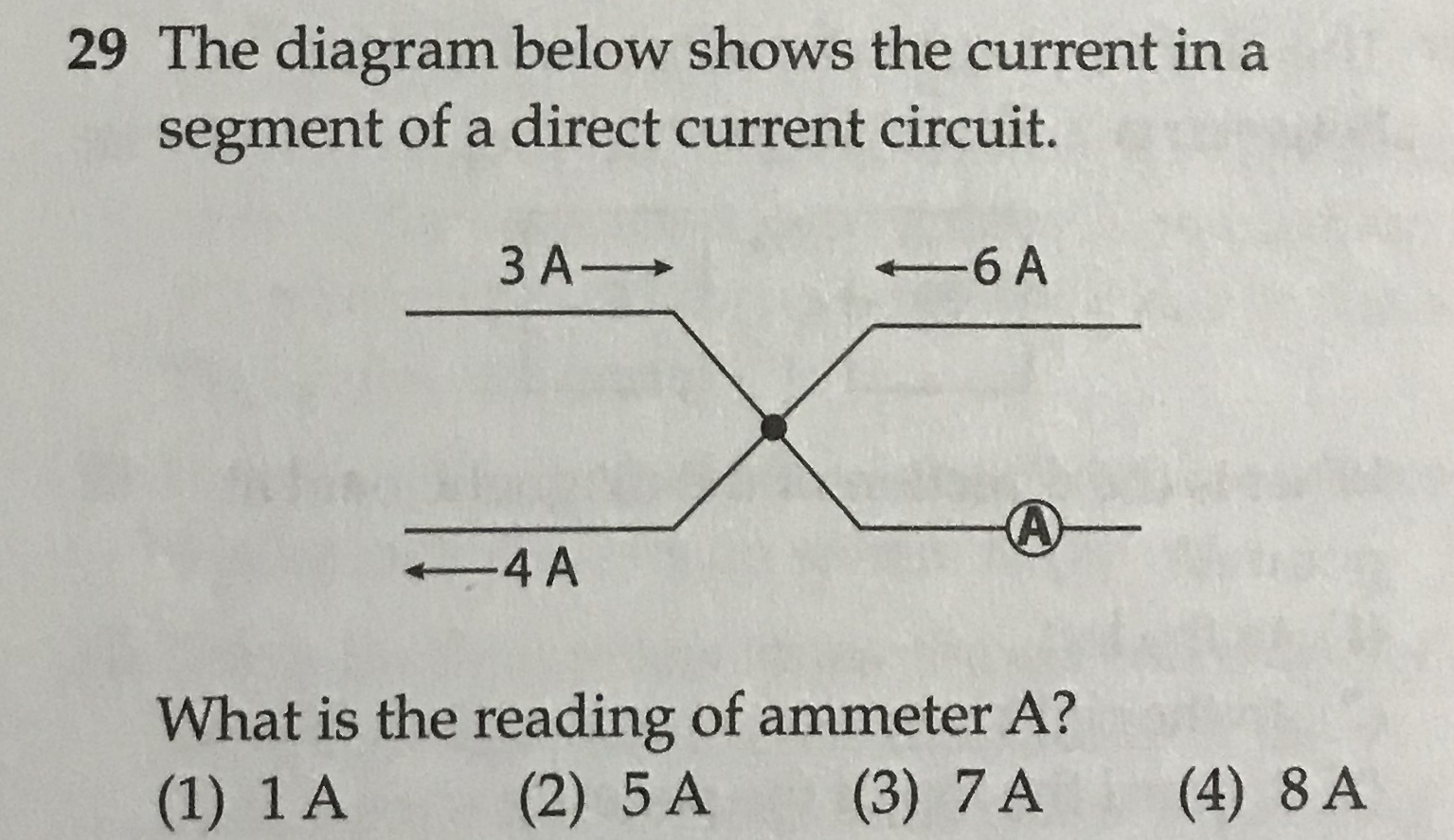
5. In the circuit shown at the right, the potential 120-volt source? A) 5 A. B) 20 A. C) 600 A. D) 12 000 A. 33. The diagram below represents currents in a segment of an electric circuit.12 pages ddmotorsystems.com › CurrentRangeHigh Performance Electric DC Motors - D&D Motor Systems Figure 12-1 shows a picture of a typical DC motor, Fig. 12-2 shows a picture of an electric DC motor armature, and Fig. 12-3 shows a picture of a typical electric dc motor stator. From the picture in Fig. 12-2 you can see the armature is made of coils of wire wrapped around the core, and the core has an extended shaft that rotates on bearings. Electric Circuits? It's All About Nodes, Branches, and Loops Since the elements of an electric circuit can be interconnected in several ways, we need to As the next two definitions show, circuit topology is of great value to the study of voltages and currents A branch in network topology is defined as a segment connecting two nodes. In Figure 1, there are thus... Answered: The diagram below shows currents in a… | bartleby Solution for The diagram below shows currents in a segment of an electric circuit. |7A 5A ЗА What is the reading of ammeter A?1 answer · Top answer: Step 1 The solution is give...
Answered: 29 The diagram below shows the current… | bartleby
How to Read Electrical Schematics - Circuit Basics An electrical schematic is a diagram that shows how all of the wires and components in an electronic circuit are connected. Power sources supply electrical energy to a circuit in the form of voltage and current. Every functional electronic circuit needs to have a DC or AC power source.
Energies | Free Full-Text | Analysis of the Current Electric ...
Parallel RLC Circuit — Collection of Solved Problems The total current through the circuit is 2.5 A. Assess the resistance of the resistor, the capacity of the ideal capacitor and the inductance of the ideal inductor (presume that IC > IL). How to draw the phasor diagram of a parallel RLC circuit: Draw the phasor of voltage along the x axis as well as the...

Electric Current Circuits in Astrophysics | SpringerLink
How does electric current know which path along the circuit to take? Similarly, in electrical circuits we manipulate the electric potential. Same concept, different force, so you The return current is confined below the signal trace and does not spread out over the entire It is very important to know the basic parts of a simple circuit and the symbols that relate to them.

Using IB symbols sketch a series circuit including
RLC Circuit Analysis (Series And Parallel) - Clearly... | Electrical4U The figure below shows the phasor diagram of the series RLC circuit. The impedance Z of a series RLC circuit is defined as opposition to the flow of current due circuit resistance R, inductive reactance, XL and capacitive reactance, XC.

Performance of Fully Stressed Design Versus Optimization ...
Circuits and components professional english in use... Simple circuits. The circuit diagrams below show lamps connected in a parallel circuit and in a series circuit. The supply has live and neutral conductors. On an alternating current (AC) supply, the difference between live and neutral is that conductors on the neutral side of appliances are earthed...

Circuits Flashcards | Quizlet
simple-circuit.com › esp8266-nodemcu-stepper-motorStepper Motor Control with ESP8266 NodeMCU - Simple Projects Jul 29, 2019 · Stepper motor control with NodeMCU circuit: Project circuit schematic diagram is shown below. The stepper motor is connected to the ULN2003A board which is supplied with external power source of 5V. The control lines (IN1, IN2, IN3 and IN4) of this board are connected to the NodeMCU as: IN1 to NodeMCU pin D1, IN2 to NodeMCU pin D2, IN3 to ...
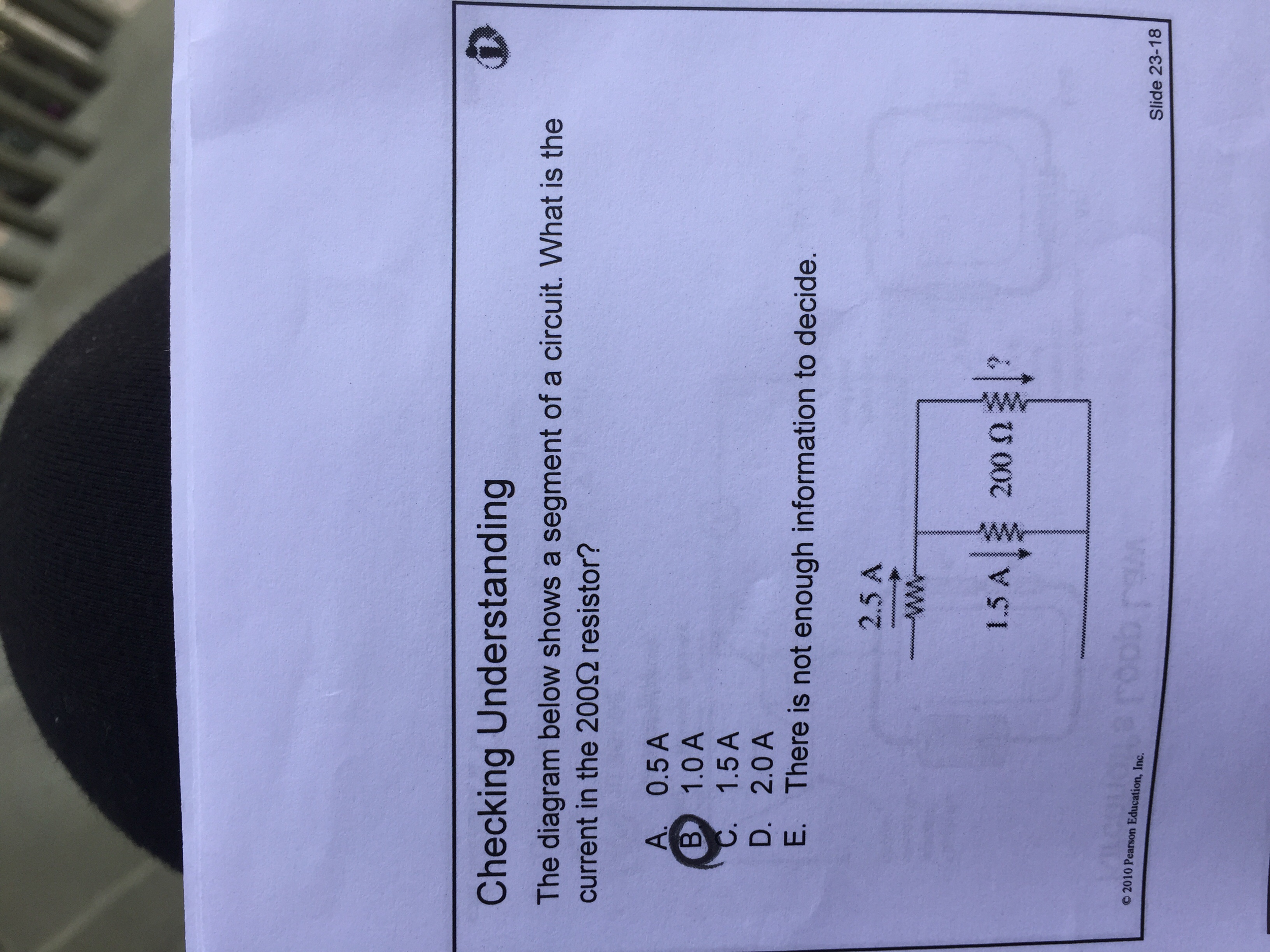
Solved The diagram below shows a segment of a circuit. What ...
IELTS Writing Task 1 Sample Answer: Hydroelectric... - How to do IELTS The diagram below shows how electricity is generated in a hydroelectric power station. In general, the diagram can be broadly separated into day and night stages with the daylight stages involving the generation of electricity from a river and storage of water in a reservoir.
What is Ground in Electronic Circuits? - Build Electronic ...
circuitdigest.com › electronic-circuits › d-flip-flopsD Flip-Flop Circuit Diagram: Working & Truth Table Explained Sep 27, 2017 · D Flip-Flop Circuit Diagram and Explanation: Here we have used IC HEF4013BP for demonstrating D Flip Flop Circuit, which has Two D type Flip flops inside. The IC HEF4013BP power source V DD ranges from 0 to 18V and the data is available in the datasheet. Below snapshot shows it. Since we have used LED at output, the source has been limited to 5V.

Search for a Tie-breaker (The Liquid Democracy Journal, Issue 2)
PDF Name | Circuits-Circuit Analysis 9. Which circuit diagram below correctly shows the connection of ammeter A and voltmeter V to measure the current through and potential difference across resistor R? 53. The diagram below represents currents in a segment of an electric circuit.
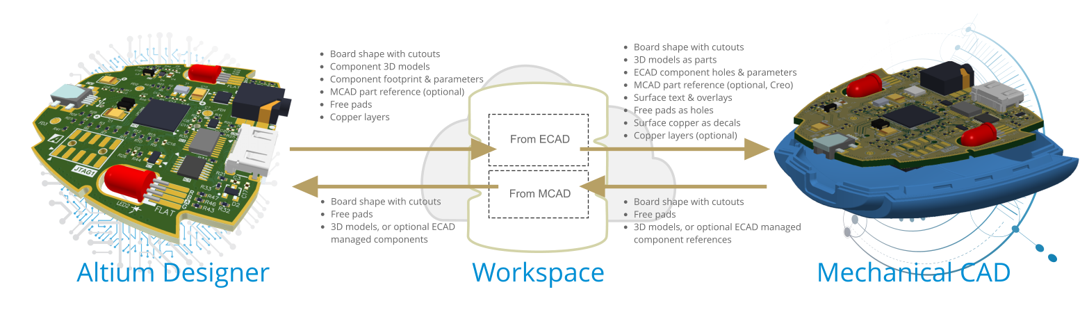
Direct ECAD-MCAD Design with Altium MCAD CoDesigner | Altium ...
Series circuits - Electric current and potential difference... If you follow the circuit diagram from one side of the cell to the other, you should pass through all the different components, one after the other, without any branches. In a series circuit, if a lamp breaks or a component is disconnected, the circuit is broken and all the components stop working.

LED circuit - Wikipedia
Electronic Circuit Symbols - Components and Schematic Diagram... In electronic circuits, there are many electronic symbols that are used to represent or identify a basic electronic or electrical device. The symbols for different electronic devices are shown below. The device has an electric field that controls the conductivity of a channel of one type charge carrier...
Circuit terminology (article) | Khan Academy
RLC Series AC Circuits | Physics Draw the circuit diagram for an RLC series circuit. Explain the significance of the resonant frequency. The crux of the analysis of an RLC circuit is the frequency dependence of XL and XC, and the effect they have on the phase of voltage versus current (established in the preceding section).
Solved plz all of it i posted this earlier and they did ...
Q1. The circuit diagram below shows a 6.0 V battery of negligible In the circuit shown in the figure below, the battery, of negligible internal resistance, is Figure 2 Explain, without calculation, why the current through the battery increases in value from that in The candidate states that the thermistor is connected in a suitable circuit with voltmeter and ammeter or...

Resistors in series (video) | Circuits | Khan Academy
Electric Circuit - Diagram, Symbol, Open and Closed Circuit - Teachoo Electric Current is flow of electrons(negatively charged particles). Electric Current moves from Extra Question 10 - A child has drawn the electric circuit to study Ohm's law as shown in Figure 12.6. Extra Question 12 - Draw a circuit diagram of an electric circuit containing a cell, a key, an...
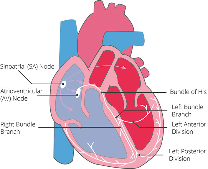
Electrocardiogram (ECG) | CardioSecur
IELTS academic writing task 1 process diagram. Model answer included. The diagram below shows how geothermal energy is used to produce electricity. Summarise the information by selecting and reporting the main features, and make comparisons where relevant. The diagram illustrates the process by which geothermal energy is used in the production of electricity.
Electricity Regents Review
Resistors in Circuits - Practice - The Physics Hypertextbook The diagram below shows a circuit with one battery and 10 resistors; 5 on the left and 5 on the right. Determine… the current through. This sets us up to get the current in all the different segments of the circuit. (The current divides and divides again in an effort to follow the path of least resistance.)
Figure below shows a portion of an electric circuit with the ...
Electric Current Definition, Formula, Unit and Circuit Diagram Electric Current and Circuit Diagram Elements. The schematic diagram represents the different components of a circuit; this is the circuit diagram. These symbols represent the common electrical components. Solved Example For You. Q. A current of 0.75 A is drawn by the filament of an electric...

A specialized spinal circuit for command amplification and ...
› dc-voltage-converter-circuitsDC Voltage Converter Circuits | Nuts & Volts Magazine During the early 1930s, engineers needed a cheap, reliable, and safe way of generating high-value low-power DC voltages from low-cost non-lethal transformers, and devised a simple two-section ‘voltage multiplier’ circuit to do this job. Figure 2 shows such a circuit, driven from the secondary winding of a 250V transformer. FIGURE 2.

Diagram representing the nature of the relationship between ...
Ch 22 Flashcards | Quizlet 12. The diagram shows the electric field lines in a region of space containing two small charged The electric field is zero at a point P between the particles on the line segment connecting them. The diagrams below depict four different charge distributions. The charge particles are all the same...

PhysicsLAB: June 2013, Part 2
Solved The diagram below shows currents in a segment of an These cookies may be set through our site by our advertising partners. They may be used by those companies to build a profile of your interests and show you relevant adverts on other sites. They do not store directly personal information, but are based on uniquely identifying your browser and internet...
Optimal Polarization Synthesis of Arbitrary Arrays With ...
Electric current - Wikipedia An electric current is a stream of charged particles, such as electrons or ions, moving through an electrical conductor or space. It is measured as the net rate of flow of electric charge through a surface or into a control volume.:
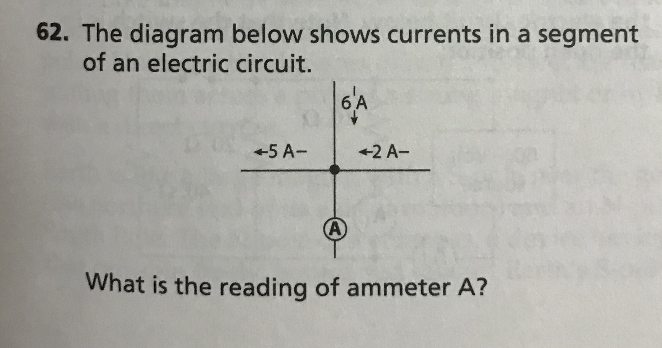
Answered: 62. The diagram below shows currents in… | bartleby
APlus Circuit Analysis Questions.pdf - Scanned Document Which circuit diagram below correctly shows the connection of ammeter A and voltmeter V to measure the current through and potential difference across resistor ...11 pages
Circuits Practice Flashcards - Easy Notecards
Skill 44: Parallel Circuits 275. Rules of Parallel Circuits The diagram below shows electric currents in conductors that meet at junction P. 2 A. IN OUT. 2A. 305. An electric circuit contains an operating heating.16 pages

Answered: 29 The diagram below shows the current… | bartleby
circuitdigest.com › electronic-circuits › clapClap Switch Circuit Diagram using IC 555 Jun 05, 2015 · Clap switch is an interesting hobby circuit which turns on the lights with a clap sound. Although its name is “Clap switch”, but it can be turned ON by any sound of approximately same pitch of Clap sound. The main component of this clap switch circuit is the Electric Condenser Mic, which has been used as a sound sensor. Condenser Mic ...
Tutorial - A Complete Design Walkthrough with Altium Designer ...
Classwork/HW Name: Date: 1. Base your answer(s) to the ... 25 Mar 2019 — [Show all work, including the equation and substitution with units.] 48. The diagram below shows currents in a segment of an electric circuit.10 pages
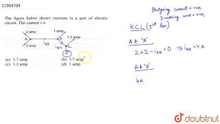
The figure below shows current in a part of electric circuit. The current `i` is
What is an Electrical Circuit? - Codrey Electronics | Circuit Diagram Electrical circuit is an interconnection of electrical components. A circuit is a closed path where electrons flow in a wire. As long as the copper wire is allowed to itself, the electrons drift between the atoms but never leave the copper.
June 2013 Physics Regents

Lesson Explainer: Magnetic Fields Produced by Electric ...
Regents Review for E-Statics, Circuits, & Magnetism
PPT - Pew Pow PowerPoint Presentation, free download - ID:2604302

Circuits — Circuit Analysis | Call Me Dr Rob
The figure shows currents in a part of an electric circuit ...

Plug-in electric vehicles in Norway - Wikipedia
Q1. The diagram shows an electrical circuit. (a) Complete the ...

The diagram below shows a segment of a circuit. What is the ...
PHY294H
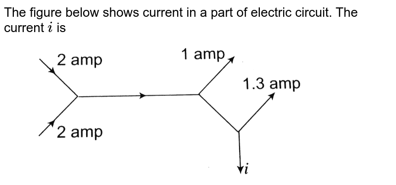
The figure below shows current in a part of electric circuit. The
Wizard Test Maker

The figure below shows currents in a part of electric circui
0 Response to "39 the diagram below shows currents in a segment of an electric circuit"
Post a Comment