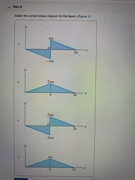
42 select the correct shear diagram for the beam
PDF Beam Design Formulas With Shear and Moment Shear and moment diagrams and formulas are excerpted from the Western Woods Use Book, 4th edition, and are provided herein as a courtesy of Western Wood Products Association. Introduction Notations Relative to "Shear and Moment Diagrams" E = modulus of elasticity, psi I = moment of inertia, in.4 L = span length of the bending member, ft. forums.autodesk.com › t5 › robot-structural-analysisSolved: Mesh nodes on panels not deleting - Autodesk Community Jan 24, 2022 · Hi, i have being trying to put a build a model, however some of the wall panels i have split using the split tools. after some of the panels have been split, i now delete the mesh in model using the delete meshing tool and the nodes on the panels are still there? i have then opened in repair mode...
W Jс В Select The Correct Shear Diagram For The Beam ... Pick the exactly shear diagram for the beam. indigenous the v diagram the shear force is the very same for all cross part of the beam. Pick the correct minute diagram for the beam. Shear and also bending moment diagram for a just supported beam with a concentrated load in ~ mid span. 0 in ~ the allude of applications of the couple.
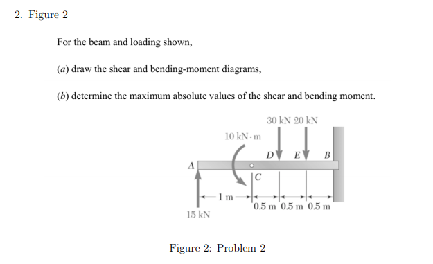
Select the correct shear diagram for the beam
Free Online Beam Calculator | SkyCiv Engineering Free online beam calculator for generating the reactions, calculating the deflection of a steel or wood beam, drawing the shear and moment diagrams for the beam. This is the free version of our full SkyCiv Beam Software. This can be accessed under any of our Paid Accounts, which also includes a full structural analysis software. Sign Convention for Shear Force and Bending Moment Diagram ... Today we will see here the sign conventions for shear force and bending moment diagram in subject of strength of materials with the help of this post. Sign conventions for shear force Let us consider that we have one beam AB and we have assumed one section XX as displayed in following figure. PDF Beams SFD and BMD - IIT Guwahati Beams -SFD and BMD V = V 0 + (negative of area under the loading curve from x 0 to x) M = M 0 + (area under the shear diagram from x 0 to x) If there is no externally applied moment M 0 at x 0 = 0, total moment at any section equals the area under the shear diagram up to that section When V passes through zero and is a continuous
Select the correct shear diagram for the beam. 42 select the correct shear diagram for the beam. - Wiring ... 42 select the correct shear diagram for the beam. Written By Elizabeth K. Casey Thursday, December 16, 2021 Add Comment Edit Draw The Shear And Moment Diagram s For Cantilever Beam. A Cantilever Beam Ab Is Subjected To Uni for mly Distributed Load As Shown In Figure Ex 3 Determine Reactions At Supports And B Draw The Shear For ce Bending Moment Diagram s. Draw the shear diagram for the beam. follow the sign ... A triaxial shear test is preferred to direct shear test, because; For a reinforced concrete section the shape of shear stress diagram is; Determine the internal normal force shear force and moment at point c; Determine the internal normal force shear force and moment at point c; Select the correct shear and bending moment diagrams Answered: Draw the shear diagram for the beam.… | bartleby Draw the shear diagram for the beam. Follow the sign convention. (Figure 1) Click on "add vertical line off" to add discontinuity lines. Then click on "add segment" button to add functions between the lines. Note 1 - Make sure you place only one vertical line at places that require a vertical line. W Jс В Select The Correct Shear Diagram For The Beam ... Choose the exactly shear diagram for the beam. from the v diagram the shear pressure is the very same for all cross part of the beam. Choose the correct minute diagram because that the beam. Shear and bending minute diagram because that a simply supported beam with a focused load at mid span. 0 in ~ the point of applications of the couple.
Solved Part A Select the correct shear diagram for the ... Engineering. Civil Engineering. Civil Engineering questions and answers. Part A Select the correct shear diagram for the beam. (Figure 1) wa 2a -wa 2wa 2wa x. 2a -2wa wa -Part B Select the correct moment diagram for the beam. 2a 2a 2a 24. Question: Part A Select the correct shear diagram for the beam. beamguru.comBEAMGURU.COM - Beam Calculator and Frame/Truss Beam ... This website is great! I was having trouble understanding some simple beam problems when being asked to draw the shear force/bending moment diagrams. Using this tool I was able to understand where I was messing up and how to correct my mistake so that I could correctly solve for my reaction forces and draw my shear force diagram. Select the Shear Force Diagram for the following beam: Select the Shear Force Diagram for the following beam: ... A beam of length L, having uniform load of W kg per unit length, is supported freely at the end. The bending moment at mid spam will be ... Choose the correct combination for the given Table : Stress-strain Graph Material A. 1. Elastic-Plastic B. 2. Rigid Plastic C. 3. Answered: Draw the shear diagram for the beam.… | bartleby Solution for Draw the shear diagram for the beam. Follow the sign convention. (Figure 1) Click on "add vertical line off" to add discontinuity lines. Then click…
PDF CHAPTER 2 Shear Force And Bending Moment a) Calculate the shear force and bending moment for the beam subjected to a concentrated load as shown in the figure. Then, draw the shear force diagram (SFD) and bending moment diagram (BMD). b) If P = 20 kN and L = 6 m, draw the SFD and BMD for the beam. P kN L/2 L/2 A B EXAMPLE 4 The Ultimate Guide to Shear and Moment Diagrams ... Similarly to equation (23), this expressions allows us to infer a qualitative shape for the bending moment diagram, based on the shear force diagram we've already calculated. Consider the shear force between A and D for example; it's constant, which means the slope of the bending moment diagram is also constant (an inclined straight line). Q 1 The bending moment diagram of the beam shown in the ... Q 1 The bending moment diagram of the beam shown in the figure is Q 2 The SFD and BMD for a beam are shown in the given figure I and II. The corresponding loading diagram would be Q3 A simply supported beam is loaded as shown in the given figure. The bending moment at E would be a. 6 t-m (Sagging) b. 4 t-m (Hogging) c. 6 t-m (Hogging) Trapezoidal Distributed Load Shear And Moment Diagram ... Bending moment diagram (bmd) shear force diagram (sfd) axial force diagram. For the distributed load to show select: Axial, shear and bending diagrams 27: Moment diagram shear diagram shear and moment diagrams uniformly distributed load cantilever beam uniformly varying load trapezoidal load.
study.com › learn › free-body-diagram-questions-andFree Body Diagram Questions and Answers - Study.com The box at the end is connected through a wire and weighs 80 N. Draw a Free-Body Diagram for the beam. View Answer If the 5 \ kg block is suspended from the pulley B and the sag of the cord is d ...
CHAPTER derive shear force and bending moment diagrams for a given fl exural member and given loading. This can be achieved by using Equations 2.7 and 2.8. However, loading on the beam for a given bending moment diagram can also be derived by using Equations 2.6. Second expression in Equation 2.6 converts the given bending moment diagram into the
Select the correct shear and bending moment diagrams Select the correct shear and bending-moment diagrams for the beam and loading shown and determine the maximum normal stress due to bending. Answer D 2 m 리 using He 25y
Bending moments and shear force | Physics Quiz - Quizizz 60 seconds. Report an issue. Q. Select the correct statement regarding the diagram: answer choices. This is a bending moment diagram. The only load is a uniform distributed load. There is a point load and a uniform distributed load. The beam only has one support at 3m from the left hand side.
› statics-simple-beamSimply supported beam diagrams : article | calcresource Dec 31, 2020 · The bending moment diagram, or BMD in short, is a diagram plotted on-top the structure, that displays the value of the bending moment at any point. Similarly the shear force diagram, or SFD, displays the value of shear force at any point of the structure while the axial force diagram, or AFD, displays the value of the axial force.
Select the correct shear and bending-moment diagrams for ... Select the correct shear and bending-moment diagrams for the beam and loading shown and determine the maximum absolute value (a) of the shear, (b) of the bending moment. Correct shear diagram: Correct...
Chapter 4 Bending Moment and Shear Force Diagram S K ... The shearing force at any section on the length BC of the member is: (a) Zero (b) P (c) Pa/k (d) Pk/a [IAS-1996] Cantilever Carrying load Whose Intensity varies IAS-9. The beam is loaded as shown in Fig. I. Select the correct B.M. diagram [IAS-1999] For-2020 (IES,GATE, PSUs) Page 199 of 493 Rev.0
PDF Chapter 4 Shear and Moment In Beams - ncyu.edu.tw It is visually desirable to draw the V-diagram below the FBD of the entire beam, and then draw the M-diagrambelow theV-diagram. The bending moment and shear force diagrams of the beam are composites of the Vand Mdiagrams of the segments. These diagrams are usually discontinuous, or have discontinuous slopes.
thenavalarch.com › designing-a-spreader-beam-forDesigning a spreader beam for lifting - TheNavalArch Aug 05, 2020 · Spreader beam vs Lifting beam. At the outset, it is important to clarify the difference between a spreader and a lifting beam. A spreader beam is designed to take primarily compressive loads, as can be seen in the figure above. If we resolve the forces on the whole beam, we get the force diagram as above.
Mastering Engineering, Assignment--12--Beams (Engineering ... Assignment12Beams Due: 11:59pm on Tuesday, April 26, 2016 You will receive no credit for items you complete after the assignment is due. Grading Policy Problem 7.52 Part A Select the correct shear diagram for the beam. ANSWER:
PDF 4. Bending Moment and Shear Force Diagram Chapter-4 Bending Moment and Shear Force Diagram S K Mondal's The upward direction shearing force which is on the left hand of the section XX is positive shear force. The downward direction shearing force which is on the right hand of the section XX is positive shear force. Negative Shear Force
roymech.org › Useful_Tables › BeamsElastic Bending Theory - Roy Mech At any point x along the beam there is a moment F(x - L) = M x = EI d 2 y /dx 2. Example - Simply supported beam. Consider a simply supported uniform section beam with a single load F at the centre. The beam will be deflect symmetrically about the centre line with 0 slope (dy/dx) at the centre line. It is convenient to select the origin at the ...
[Solved] The correct shear force diagram for the ... The correct shear force diagram for the cantilever beam with uniformly distributed load over the whole length of the beam is - ... The Bending Moment Diagram of a cantilever beam subjected to moment at free end of beam will be: ... Choose the correct combination for the given Table : Stress-strain Graph Material A. 1. ...
Draw the shear diagram for the beam. follow the sign ... Draw the shear diagram for the beam. Follow the sign convention. (Figure 1) Click on "add vertical line off" to add discontinuity lines. Then click on "add segment" button to add functions between the lines. Note 1 - You should not draw an "extra" discontinuity line at the point where the curve passes the x-axis.
› support-center › generalIDEA StatiCa Connection Theoretical background The shear lug consists of shell finite elements and is checked as regular plates. Also, the welds of the shear lug to the base plate are checked using standard procedures in IDEA Connection. Manual calculation usually assumes beam theory for the shear lug, although it is not accurate because the length to width ratio is very small for shear lug.
PDF Beams SFD and BMD - IIT Guwahati Beams -SFD and BMD V = V 0 + (negative of area under the loading curve from x 0 to x) M = M 0 + (area under the shear diagram from x 0 to x) If there is no externally applied moment M 0 at x 0 = 0, total moment at any section equals the area under the shear diagram up to that section When V passes through zero and is a continuous
Sign Convention for Shear Force and Bending Moment Diagram ... Today we will see here the sign conventions for shear force and bending moment diagram in subject of strength of materials with the help of this post. Sign conventions for shear force Let us consider that we have one beam AB and we have assumed one section XX as displayed in following figure.
Free Online Beam Calculator | SkyCiv Engineering Free online beam calculator for generating the reactions, calculating the deflection of a steel or wood beam, drawing the shear and moment diagrams for the beam. This is the free version of our full SkyCiv Beam Software. This can be accessed under any of our Paid Accounts, which also includes a full structural analysis software.
![Solved] The part of the shear force diagram for a beam is ...](https://storage.googleapis.com/tb-img/production/20/06/F4_S.C_Madhu_21.05.20_D%206.png)


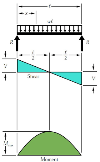

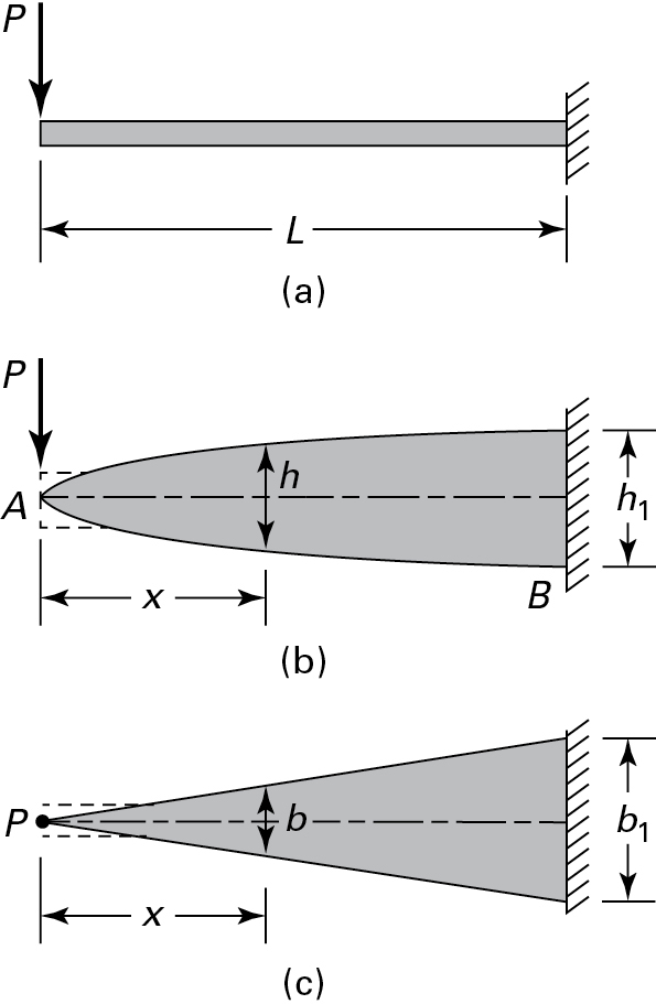


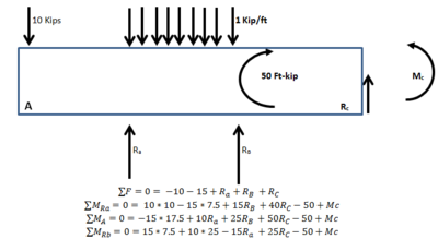









0 Response to "42 select the correct shear diagram for the beam"
Post a Comment