40 free body diagram simulator
In the forces and free-body diagrams simulation, you will create free body diagrams for a mass attached to a spring, a mass being underwater and a mass rolling down a hill. Change the magnitude of these forces – how will they affect the motion of the mass? Explore Forces and Free-body Diagrams: Learn how to navigate a drone Virtual Lab Simulation The Free Body Diagrams Interactive is a skill-building tool that allows the learner to interactively construct free-body diagrams for 12 physical situations. Each situation is described and the learner clicks/taps on-screen buttons to select forces that are directed upward, downward, rightward and leftward.
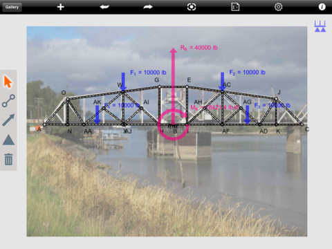
This free online structural frame calculator will generate and find the bending moment and shear force diagrams of a 2D frame structure. The free version allows you to input frames with a maximum of 3 members with applied point loads and moments for 2D frame analysis.

Free body diagram simulator
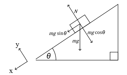
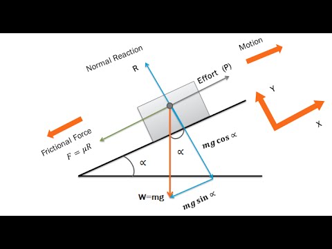
Every equilibrium problem begins by drawing and labeling a free-body diagram! Creating Free Body Diagrams. The basic process for drawing a free body diagrams is. Select and isolate an object. The "free-body" in free-body diagram means that the body to be analyzed must be free from the supports that are physically holding it in place. If you view the free-body diagram, you will see the radial and tangential components of the force of gravity acting on the ball, the force the rod exerts on the ball, and the damping force (if damping is not zero). Simulation written by Andrew Duffy, and first posted on 8-03-2017. Updated version posted on 8-07-2017. https://imgur.com/a/g6QvNX5 If you’re given the applied force, would you draw another arrow next to the parallel component (mg sin theta), or is the parallel component the applied force?
Free body diagram simulator. The math behind the simulation is shown below. Also available are: open source code, documentation and a simple-compiled version which is more customizable. For small oscillations the simple pendulum has linear behavior meaning that its equation of motion can be characterized by a linear equation (no squared terms or sine or cosine terms), but for larger oscillations the it becomes very non ... The road input u is modeled as a step input, with a rising edge and falling edge.v1 is the vertical translational speed of the body of the vehicle and v2 is the vertical translational speed of the wheel.. All the initial conditions of the integrators are set to zero. The simulation is set to run for 8 seconds.. The results of the simulations are saved in the Scilab workspace, under the ... Any changes made will automatically re-draw the free body diagram any simply supported or cantilever beam. The beam reaction calculator and Bending Moment Calculations will be run once the "Solve" button is hit and will automatically generate the Shear and Bending Moment Diagrams. Construct free-body diagrams for the following physical situations. Label all forces (e.g, Fgrav, Fnorm, Fapp, Ffrict, Fair, Ftens, etc. ). a. A physics book rests upon a level table. b. A skydiver is falling and has reached a terminal velocity. c. A large crate is being
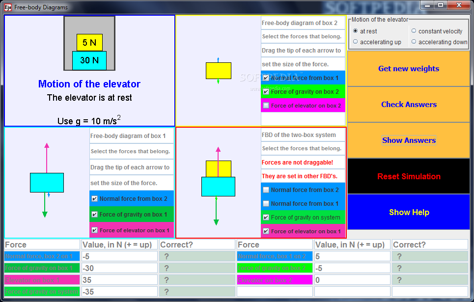
Jul 16, 2016 · This simulation offers users the opportunity to sketch free-body diagrams relating to a one-dimensional situation. Two boxes are stacked one atop the other. The bottom box rests on the floor of an elevator, which may be at rest, moving with constant velocity, or accelerating. So, for context, imagine a small toy car of mass m\_1 on a table parallel to the ground. The back of the car is attached to a string. That string is fed through a small pulley wheel at the edge of the table and the other end of the string is attached to a hanging weight of mass m\_2. In addition to this, there is a motion sensor at the other end of the table, directly opposite the car. Finally, there is a magnet attached to the back of the car (its mass is included in m\_1) as well as a magnet n... Hi friends have a basic physics question I'm having trouble understanding. So the situation is that there is a truck accelerating to the right, and there is a box on the truck that isn't moving. If I were to draw a free body diagram for just the box, there would be the normal force, weight force, and the static friction force pointing to the right that is preventing the box from moving. The box isn't accelerating since it's not moving, so what force am I missing that is pointing to the left? Explore the forces at work when you try to push a filing cabinet. Create an applied force and see the resulting friction force and total force acting on the cabinet. Charts show the forces, position, velocity, and acceleration vs. time. View a Free Body Diagram of all the forces (including gravitational and normal forces).
To explain the rules for drawing a free-body diagram. To distinguish forces that are external to the system from internal forces. To illustrate that a free-body diagram must only include the external forces acting on the considered system; To construct free-body diagrams for different situations. Learn more I'm building a climbing training apparatus in my garage that both rests on the ground and hangs by a rope from a hook attached to a ceiling joist. I'm missing something from my free body diagram that's keeping me from setting up and solving my equilibrium equations. I have the full problem laid out, with included pictures and diagrams, at the StackExchange post [here](https://physics.stackexchange.com/questions/674883/statics-question-free-body-diagram-help-for-garage-construction-project). I'... Physics Simulation: Free-Body Diagrams - Physics Classroom Save www.physicsclassroom.com. The Physics Classroom » Physics Interactives » Newtons Laws » Free Body Diagrams » Free Body Diagram Interactive. Using the Interactive The Free Body Diagram Interactive is shown in the iFrame below. There is a small hot spot in the top-left corner. Description This resource includes an interactive simulation of a person in an elevator and can simulate riding upward or downward two different distances. There is a free body diagram of the person next to the image of the elevator and as the elevator moves the free body diagram changes to reflect the changing forces.
Free Body Diagram - an overview | ScienceDirect Topics
Sometimes you see the tension of a rope included in a free-body diagram where it is actually an *internal* force for that system. In other words, both the action and its reaction are drawn in the same FBD, but to do it correctly you would actually need 2 separate FBDs. In engineering it is a big no-no to draw internal forces in an FBD.

This interactive skill-building exercise allows learners to ...
https://goengineer.com/training... For information about our training coursesThis video shows the differences between SOLIDWORKS Simulation 2019 and below an...

SOLUTION: University of Colorado Boulder Forces and Motion ...
You can list the free body forces at selected faces, edges, vertices, or components. The forces can come from contact, external loads, restraints, or connectors. To access this PropertyManager, run a static study with Compute free body forces selected on the Options tab of the Static dialog box. Right-click the Results folder and select List ...
2D-Free body diagram of first design A numerical simulation ...
Zygote Body is a free online 3D anatomy atlas. View, isolate, and learn human anatomy structures with Zygote Body.
5.7 Drawing Free-Body Diagrams | University Physics Volume 1
Learn how to draw free body diagrams. Click Create Assignment to assign this modality to your LMS. We have a new and improved read on this topic. ... Free Body Simulation Free Body Simulation. Learn how to draw free body diagrams. Full Screen. Show Hide Details . Show Hide ...

PHeTForcesandFBDLab.docx - Name Phet Forces and Free Body ...
Hi! I'm currently studying OVS's SPH4U course. I'm wondering if anybody can help me by laying out all the steps to follow when drawing free body diagrams. I just found the video instructions too unclear and hard to follow. Thanks!
lab.docx - Name Phet Forces and Free Body Diagrams Lab Net ...
7. Use the free-body diagram given on the simulation, find value of all three forces. Electric field = 20.0 N/C Charge = 10.0 microC mass = 20.0 milligrams = Angle = 45.0 degrees ; Question: 7. Use the free-body diagram given on the simulation, find value of all three forces.

Free Body Diagrams | CK-12 Foundation
Note that, on the free-body diagram, all three forces are along the vertical line passing through the center of the box, but the force of gravity and the normal force have been shifted a little so they can be seen more easily. Simulation by Andrew Duffy. Amended on 8-16-2016 to include labels on the force vectors.
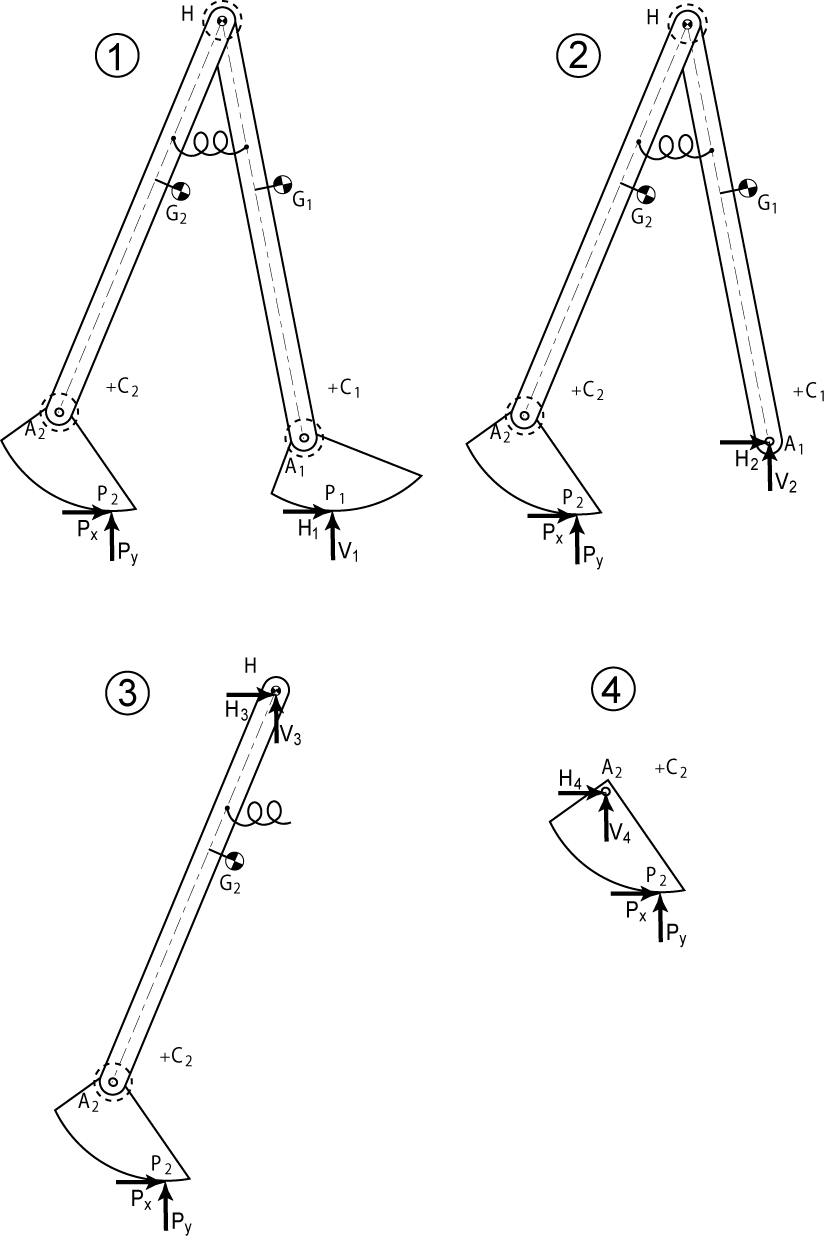
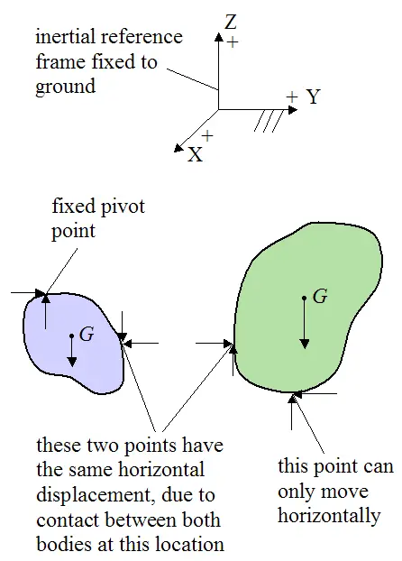
Solved 1. Draw two separate free-body diagrams for the ...
Nov 10, 2015 · Forces, Free Body Diagrams. Simulation (s) Forces and Motion: Basics (HTML5), Forces and Motion: Basics. Author (s) Kara Quinlan. Contact Email. kquinlan@hightechhigh.org. School / Organization. High Tech High Chula Vista.
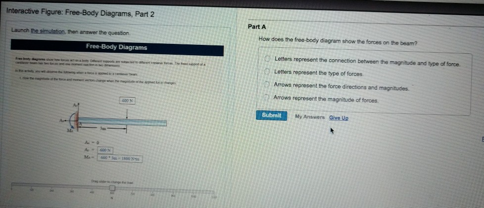
Solved Interactive Figure: Free-Body Diagrams, Part 2 Part A ...
I'm building a climbing training apparatus in my garage that both rests on the ground and hangs by a rope from a hook attached to a ceiling joist. I'm missing something from my free body diagram that's keeping me from setting up and solving my equilibrium equations. I have the full problem laid out, with included pictures and diagrams, at the StackExchange post [here](https://physics.stackexchange.com/questions/674883/statics-question-free-body-diagram-help-for-garage-construction-project). I'd...
GitHub - jamoozy/obrik: Sketched free body diagram simulator
Heat, calorimetry, ideal gas and expansion. The static and dynamic problems are entered constructing the free body diagrams of the objects. Although FisicaLab is easy and intuitive, we recommend you read the documentation first. You can access these files in the option menu Info -> Help (or FisicaLab -> Info -> Help ).

Physics Simulation: Free-Body Diagrams
orbitsimulator.com
Extra Credit 5
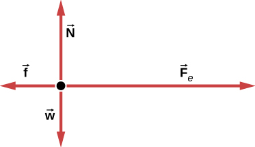
Free Body Diagram Simulator!! : A hockey puck glides to the right across the ice at a constant speed. Ignore air Situation resistance. Norm Grav : A football, originally kicked at a 400 angle.to the horizontal, is at the peak of its Situation trajectory. Ignore air resistance. Grav

Acceleration-based free-body diagrams of VR environment and ...
Learn about Newton's Third Law, force calculations in two dimensions, and the interaction of multiple objects in the context of a horse pulling a cart using our interactive simulation. Horse and Cart (Free Body Diagrams, Problem Solving Using Free Body Diagrams) | Physics | CK-12 Exploration Series
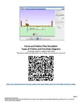
Phet Simulation Worksheet - Forces and Motion: Friction and ...
Hi! This problem is a practice exercise from the 'Introduction to Engineering Mechanics' course in Coursera. The main problem is that I don't understand what I'm being asked. I also have no idea what does M=m1/m2 mean. I would like an explanation on what is being asked. I would also like if someone solved it. I've tried using this formula: X = (m1)(x1)+(m2)(x2)/m1+m2 but I couldn't move from there. Here is the problem. Link: [Imgur: The magic of the Internet](https://imgur.com/a/F6HFVeN) ...
Dynamic Walking MATLAB Simulation Guide
The Free Body Diagrams Interactive is an adjustable-size file that displays nicely on smart phones, on tablets such as the iPad, on Chromebooks, and on laptops and desktops. The size of the Interactive can be scaled to fit the device that it is displayed on.

SOLIDWORKS 2020 What's New – Free Body Forces for Nonlinear ...
Download Free Body Diagram Simulator Software Advertisement MB Free Body Mass Index v.1.0 MB Free Body Mass Index is an interesting health software that calculates the body mass index of a person which is calculated from the body height and weight. This index is an indicator of body wellness and lets a person know where he stands.
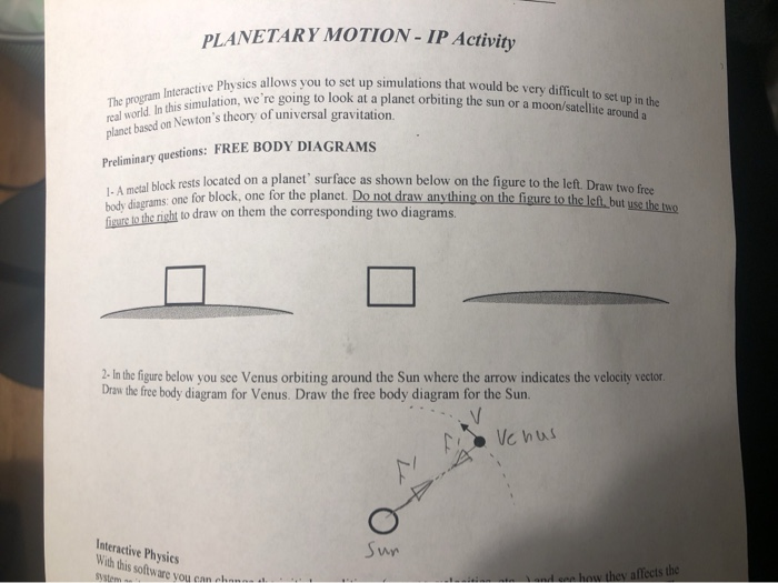
Solved PLANETARY MOTION- IP Activity The program Interactive ...
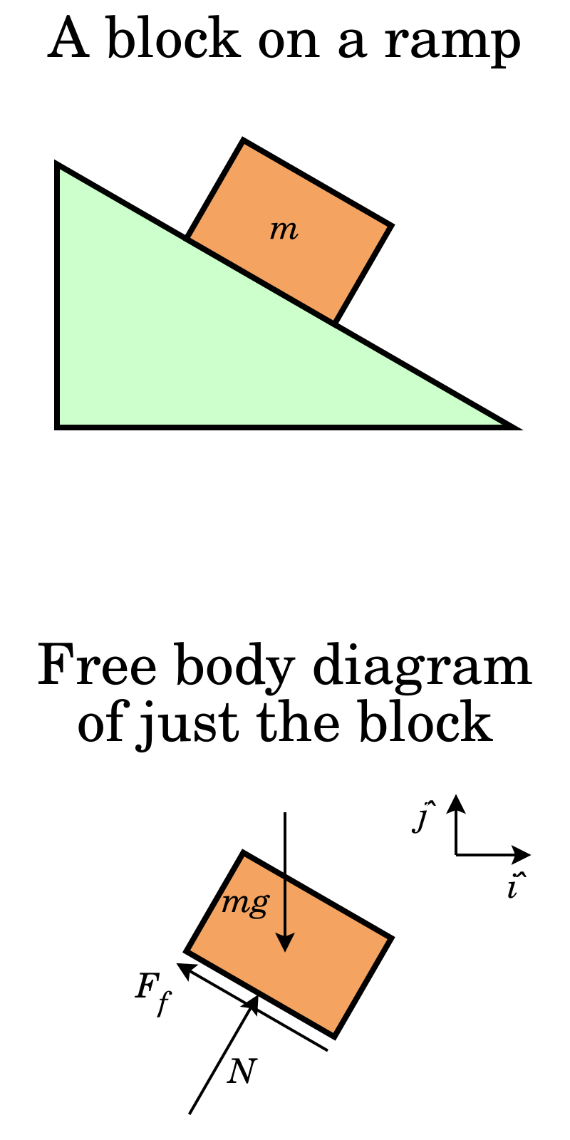
sorry if this question is a lil stupid compared to the things i see on here but i’m struggling. when i’m greeted with a problem where i have to draw a free body diagram i can do that just fine, but my problem arises when i try to write formulas. for example, on a problem, “a 650 N crate slides done the 38° ramp of a large U-haul truck at 2.2 m/s^2. find the coefficient of kinetic friction between the crate and the ramp.” my problem is comes when i try to write the formulas such as fn = fw - fv. ...
Free body diagrams and the visuo-haptic simulation | Download ...
Free body diagrams and Simulation. What is the best way to translate from a free body diagram to a usable structure for Simulation? What I am looking for is a quick way to compare different free body diagrams so I can compare the resulting compression and tension values for each part.

The Free-Body Diagram of A-FLoW in MATLAB simulation ...
Download scientific diagram | Free body diagrams and the visuo-haptic simulation from publication: Visuo-haptic Simulations to Improve Students' Understanding of Friction Concepts | Friction and ...

A free body diagram of the electrostatic simulation revealing the ...
https://imgur.com/a/g6QvNX5 If you’re given the applied force, would you draw another arrow next to the parallel component (mg sin theta), or is the parallel component the applied force?
Free body diagram - Wikipedia
If you view the free-body diagram, you will see the radial and tangential components of the force of gravity acting on the ball, the force the rod exerts on the ball, and the damping force (if damping is not zero). Simulation written by Andrew Duffy, and first posted on 8-03-2017. Updated version posted on 8-07-2017.

Pin on Sugar Cookie - Science
Every equilibrium problem begins by drawing and labeling a free-body diagram! Creating Free Body Diagrams. The basic process for drawing a free body diagrams is. Select and isolate an object. The "free-body" in free-body diagram means that the body to be analyzed must be free from the supports that are physically holding it in place.
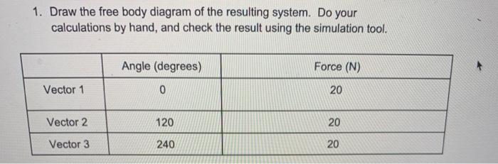
Solved 1. Draw the free body diagram of the resulting | Chegg.com

Gallery of The MaoHaus / AntiStatics Architecture - 33

AP1.Projectile Motion Simulation.pdf - Name Date Pd ...

A: free body diagram of the 2-link (feet rest-of-body ...
Drawing Free-Body Diagrams
Free Body Diagram
Download Free-body Diagrams
How to Draw a Free Body Diagram - PART 1

SOLIDWORKS Simulation: Reaction Moment Using Solid Element ...

SOLIDWORKS Simulation 2020 Free Body Forces
FBD - The Free Body Diagram Method. Kinematic and Dynamic ...
General Physics 1 Lab - PHY 2048L Name Lab 3: Ramp – Forces ...
Diagram of n-DoF preloaded structures. In a) a n-DoF free ...
Autodesk adds force simulation to iPad app lineup • GraphicSpeak
Virtual Labs
Free-body diagram | How to Draw Physics Diagrams in ...

NEW at The Physics Classroom:... - The Physics Classroom ...
0 Response to "40 free body diagram simulator"
Post a Comment