38 nos relay wiring diagram
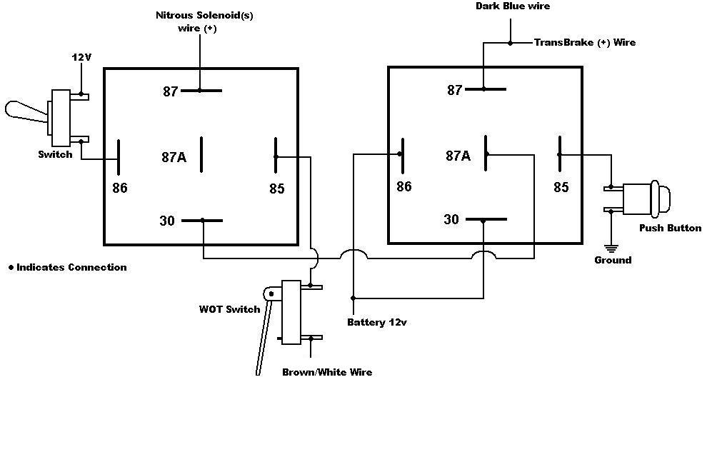
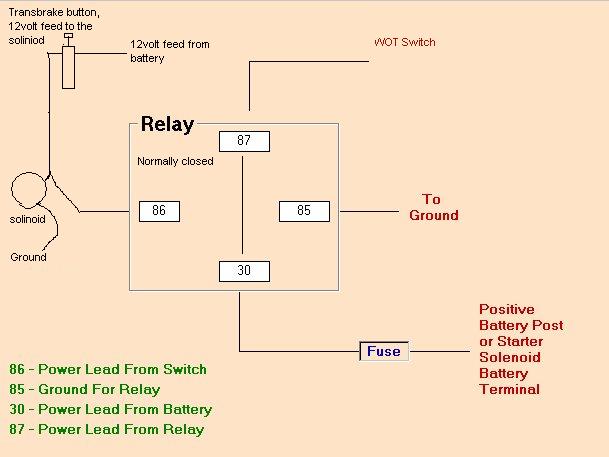
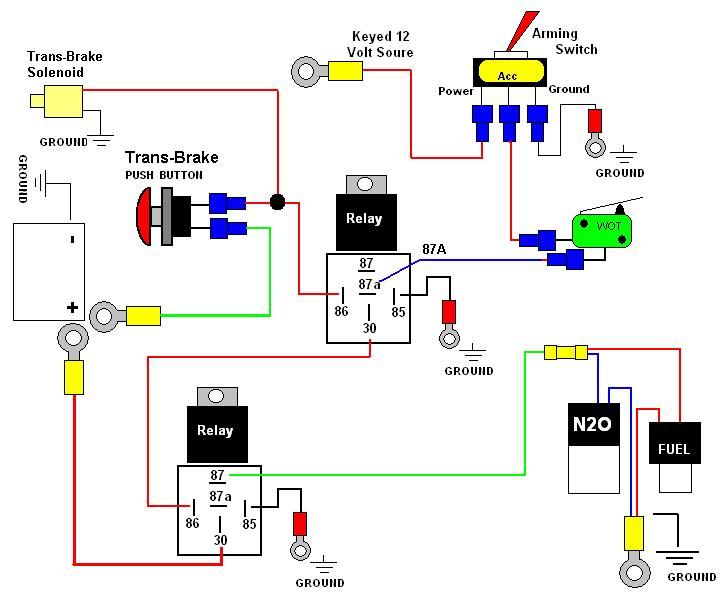
this document and the designs or information contained within are the sole property of nitrous outlet and may not be copied, distributed or made available to others without permission. nitrous outlet project: universal single stage wiring diagram filename: universal single stage wiring diagram.ai created date: 08/10/2020 pages: contact ... WIRING DIAGRAM FOR N 2O WITH TRANSBRAKE NOS P/N 15838 NOS P/N 15618 NOTES: 1) Bottom view of all relays 2) All relays must be diode suppressed N4~N 2O N4~N 2O N/C N/O COM TRIG GND 12 Volt from Transbrake Battery Ground 87 87A 30 86 85 Fused and Switched 12 Volts lts Micro Switch Arming Switch NOS DELAY TIMER DIODE SUPPRESSED RELAY #1 NOS P/N 15640
Jan 02, 2022 · The EFI trigger wire seems to act like an antenna, so if the power source isn't clean or the spark box wiring is running near ignition or alternator wiring that could be an issue. For a quick test you could temporarily connect the spark box trigger wire and the EFI trigger wire directly to the battery to see if the system wants to go into ...

Nos relay wiring diagram
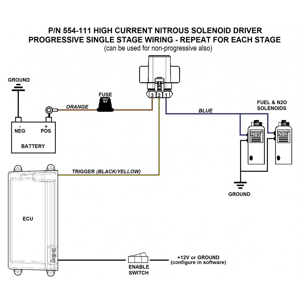
Nitrous Express Relay Wiring Harnesses Only. These relay wiring harnesses from NOS can be used with standard nitrous systems to allow you to make the right connections. NOS relay wiring harnesses have a range of uses, but one main goal--reliability. Don't settle for an inferior product--equip your ride with NOS quality relays. Most relays have five flat-blade terminals protruding from them. Those five connections are labeled numerically to identify each position's function. The No. 30 connection connects directly to a... Solenoid. Battery Ground. WIRING DIAGRAM FOR SINGLE STAGE N2. O WITH TRANSBRAKE. WITH OPTIONAL FUEL SAFETY SWITCH. NOTES: 1) Bottom view of all relays.1 page
Nos relay wiring diagram. Apr 09, 2011 · If our power supply is 200 VAC 3 phase,we need to connected the cooper bar terminal in DELTA position.It mean, a connection are U1 with W2,V1 with U2 and W1 with U2.It just need to follow the diagram shown in motor nameplate. connections and wiring diagrams. 6. Carefully open the nitrous bottle and verify that no fittings or hoses are leaking. Correct any leaks before proceeding. 7. Do not start the engine if nitrous has been accidentally injected while the motor was not running! All nitrous must be cleared from the engine before starting; otherwise a violent intake ... duty relay. (See wiring diagram). 8. Attach the white wire of the relay to ground. If using an optional fuel safety switch connect the switch.10 pages The engine control relay is the main relay that is used to enable and disable power to the engine management components. The Elite 2500 has one dedicated engine control relay output (DPO 6 (Black/Red)) capable of sinking 1A Max current ( ie 5 x 80 ...
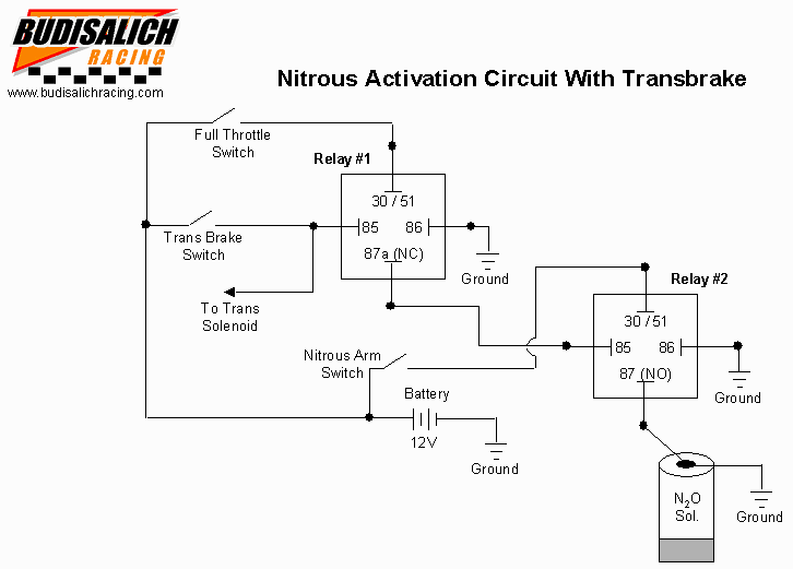
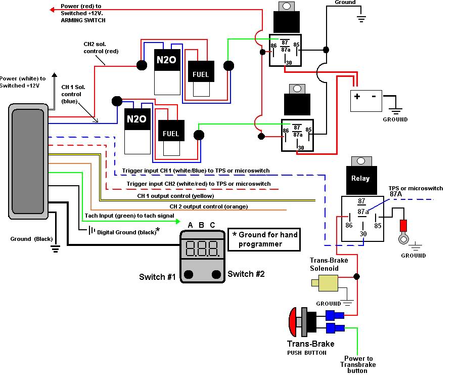
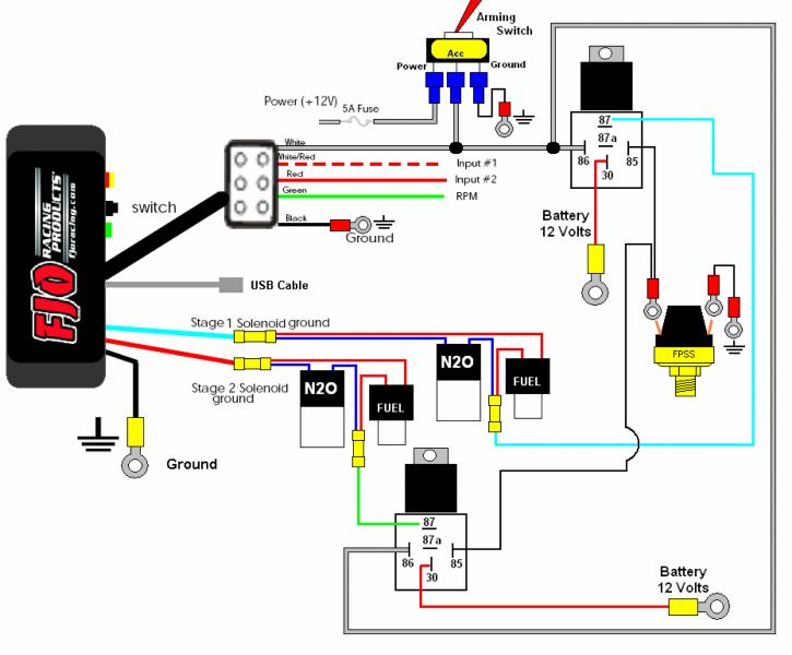
Nitrous Wiring Diagram With Transbrake. The stud labeled "2" is for the transbrake. It is activated by applying +12volts. If you have any questions, email daver@wiringall.com or call When wired in series with your nitrous system relay it will enable you plished by splicing into the trans brake solenoid wiring and using this power source to. Yes, you need a relay. Search the web for a typical Nitrous wiring diagram, should be easy to find. 40 amp min on the relay. Ron 4 Chapter 1 Product Overview The NOS Launcher Progressive Nitrous Controller is a fully featured progressive nitrous controller offering control of up to 4 individual stages . These features make this the most advanced nitrous control system on the market. A master controller controls two stages and The activation trigger is typically connected to your Nitrous System Throttle Switch, so choice if that is a positive or negative circuit. See wiring diagrams for an example. Ground Trigger is often used for EFI systems or more advanced Nitrous Progressive Controllers like the NMS1000 or AMS-2000 use the ground triggered method.
NOS have addressed the need for a reliable, rugged and affordable relay for controlling various electrical equipment on a race car. Originally designed to control the high current switching loads of nitrous solenoids, this solid state relay can also be used to control other high current devices such as electric water pumps, trans brakes & line locks. It has an ultra-low activation/release time ... Nos Relay Wiring Diagram from tse1.mm.bing.net Print the electrical wiring diagram off and use highlighters to be able to trace the routine. When you make use of your finger or even the actual circuit with your eyes, it is easy to mistrace the circuit. One trick that I actually 2 to print out the same wiring plan off twice. Mar 27, 2013 · Pico 5591PT (Relay/Wiring Kit) Pico 5593PT (Sealed Relay/Wiring Kit) Echlin/Napa AR143 (Wiring Kit) Echlin/Napa AR204 (50 amp, diode protected - correct wiring polarity required.) It can be a Micro Relay if size is a concern (LINK 5-pin with diode suppression, LINK 4-pin with resistor suppression). If you are upgrading your existing system, do not follow the wiring diagram from your original instructions. Use only the diagram shown here. Begin by mounting ...1 page
Digital Delay - Nitorus Boards : High Current 2-Stage Nitrous ...
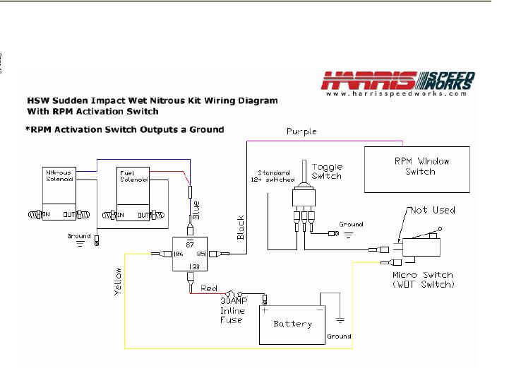
Nitrous Wiring Diagrams. by John Heard Last Updated Jan 4, 2015. Single Stage NOS System with Transbrake Interrupt Relay. Single Stage NOS System with Transbrake Interrupt Relay, MSD Window Switch, and Dynotune Delay Timer. Single Stage NOS System with Transbrake Interrupt (No Relay), MSD Window Switch, and Dynotune Delay Timer. Single Stage ...
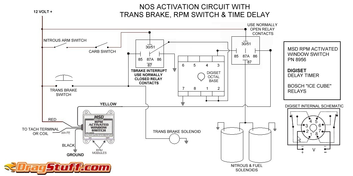
Nitrous System Wiring Diagrams - Dragstuff
Transbrake and NOS controller wiring. This is the controller i am using on my car (pn 15835BNOS) with a Cold Fusion plate kit. Basically, i'm needing a wiring diagram for wiring it up where it activates as soon as i let off the transbrake. I know there are a couple different ways to wire it (1 or 2 relays).
Nitrous Oxide System Installation Help | Cold Fusion Nitrous
outstanding nitrous express wiring diagram gallery best image of nitrous express wiring diagram 1 in nitrous express wiring diagram, nx 4 valve mustang plate.Read the tech article on Wiring Electrical Relays Into A Nitrous System, brought to you by the experts at Chevy High Performance Magazine.
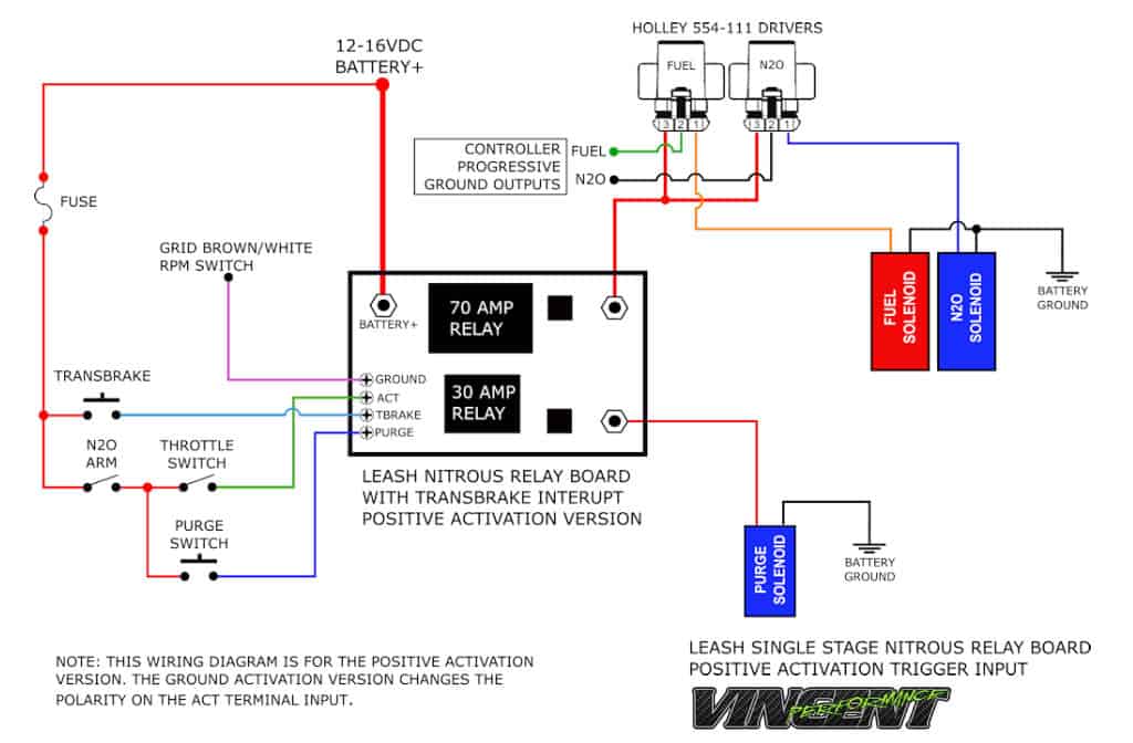
Leash Single Stage Nitrous Relay Board with Transbrake ...
WIRING DIAGRAM FOR 2 STAGE N 2 O WITH TRANSBRAKE NOS P/N 15838 30 NOTES: 1) Bottom view of all relays 2) All relays must be diode suppressed N1~N 2O N/C N/O COM TRIG GND 12 Volt from 87A 85 Transbrake Battery Ground 86 87 30 86 87 87A 85 ...
nitrous wiring? | Nitrous | Hayabusa Owners Group
An old or worn fuel pump may produce a noticeably loud whine or howl while running. If I wait an hour or so, it will start no problems. Mar 24, 2020 · Vs Commodore Wiring Diagram Pdf – wiring diagram is a simplified customary pictorial representation of an electrical circuit. Waiting 10 minutes or so and all comes good.
Nitrous/WOT/TPS install help!! | SVTPerformance.com
Nitrous Oxide Install instructions / directions. Step by step pictures and diagrams to help you install your nitrous kit.Systems and components are the quickest and easiest way to get large horsepower increases with a minimum of engine modifications and expense. Nitrous Kits offer serious horsepower at the flip of a switch.
2 step and nitrous wiring help
Hi there, I have a question about how to wire up a nitrous system. These are the parts I have. Ford MSD Distributor 8582, RPM Window Switch 8956, MSD 3-Stage Retard Control 8970, MSD High Current Relay 8960 and I want to run this all to a Nitrous System with 100-150 shot. I am also running a 3 Step but I use that for my linelock and trans brake.

nitrous outlets relay question - CorvetteForum - Chevrolet ...
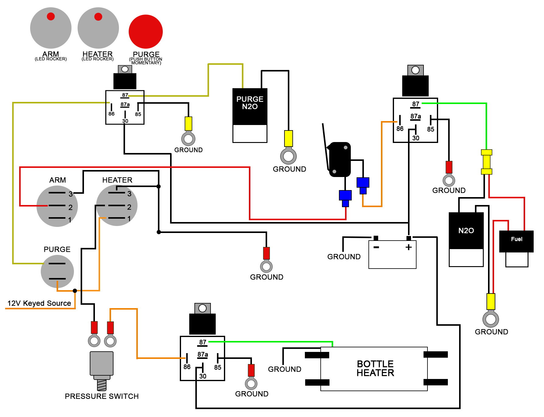
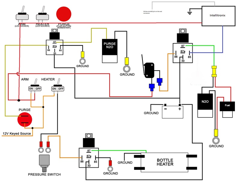
These Wiring Diagrams will help you wire up your Nitrous System or Nitrous Accessory. Includes Nitrous Purge, Nitrous Bottle Heater, and Dedicated Fuel System. Your #1 Source for everything Nitrous. Dealer Locator Account. Toggle navigation 254-848-4300 Speak with a Nitrous Expert M-F 8:30am - 5:30pm CST Call or Text Today! ...
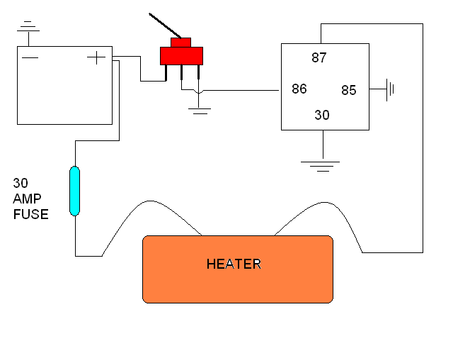
Nitrous Bottle Heater Wiring Instructions
Mainboard Installation Schematic. 1 Stage Nitrous Using 12 Relay Controller. Nitrous Controller Instructions. 4 Stage Instructions Generic for All Controllers. 4 Stage Nitrous Controller with Main Board and Auxiliary Module Installation Schematic. 3 Stage Nitrous Controller (2 Timed, 1 Instant) with Main Board and Auxiliary Module Installation ...
Wiring Diagrams
Porsche refers to the electrical switches, instrument and lights in a 356 under the very generic term, "Body Electrical" and that's where we've put all of the pieces-parts you need to keep your 356 happy from an electrical perspective.
wiring up all the nitrous goodies - Third Generation F-Body ...
Registered. Joined Jul 6, 2005. ·. 4,950 Posts. #6 · Dec 23, 2005. Only show this user. If you get no where with this PM me, I have a diagram get me your email and I will send it out or if you tell me every componet for the nitrous your running I can custom build a diagram for yor application. progressive, trans brake, retard module Etc.

Nitrous Kit wiring | Ford Mustang Forums
Feb 04, 2022 · Assortment of onan emerald 1 genset wiring diagram. Remove the screw that attaches the carburetor bowl to the bottom of the carburetor, drain the Cummins 5500-Watt RV LP Propane Generator for Motorhomes, Truck Campers, and Trailered RVs—In Stock, Ships Free from Norwall in 1-2 Days.
Nitrous Related Wiring - Page 15 - LS1TECH - Camaro and ...
Nov 25, 2014 · Don’t forget that NOS amplifiers may be working now, but how long will it be before they have capacitor issues? The Bose amplifier relay (CC # 244409) is located under the passenger side dash on 1984-1989 cars. Unfortunately, you can only feel the relay, but the wiring is visible from under the dash.
Nitrous purge not working | Page 3 | Dodge SRT Forum
Snowmobile nitrous kits are the best way to make big power! More affordable than boondockers or bossnoss. Nitrous Oxide Kits Systems and components are the quickest and easiest way to get large horsepower increases with a minimum of engine modifications and expense. Nitrous Kits offer serious horsepower at the flip of a switch.
TIME-BASED PROGRESSIVE NITROUS CONTROLLER INSTALLATION ...
relay. If someone would share the wiring diagram, it would be great. I would like to use my transbrake & bump box for staging. 2 that are normal, and one Holley "Nitrous Driver" (which is a solid state relay) for PWM.
Wiring help for my nitrous kit - CorvetteForum - Chevrolet ...
When wired in series with your nitrous system relay it will enable you plished by splicing into the trans brake solenoid wiring and using this power source to. Mar 29, Nitrous Oxide - wiring diagram of 2 step, NOS throttle switch and I need to 2 step and transbrake at rpm or so and have my NOS. Wiring your nitrous kit has NEVER been so easy!

nitrous wiring question - Page 2 - EvolutionM - Mitsubishi ...
How do I got about wiring in and configuring the ECU to control the relay for the nitrous solenoid and fuel enrichment? Page 3, Wiring Diagrams Wiring Diagram #1 Factory Harness to Horn Horn To Nitrous Bottle Wiring Diagram #2 Factory Harness to Horn Horn To Nitrous Bottle 2007 Edelbrock Corporation Brochure #63-71940 +12V with Key On Black ...
nitrous wiring? | Nitrous | Hayabusa Owners Group
power all devices being switched ON by the relay. 6. Connect the remaining Blue wire to the device, such as nitrous and fuel solenoids, you wish to turn ON with the relay. 7. It is advisable to connect an in-line fuse holder, or circuit breaker between the relay and the power source of a suitable capacity to protect the relay

15974 NOS mini - faulty? wiring? grounding solenoids when ...
existing NX relay and plug the Max EZ male plug into your NX relay harness. If your nitrous system does not have a standard NX relay harness, use the included NX relay harness to complete the installation. The following diagrams show installation with popular accessories. Select the appropriate diagram
2 Step Nitrous Latching Relay 7531 - Holley Motor Life
Solenoid. Battery Ground. WIRING DIAGRAM FOR SINGLE STAGE N2. O WITH TRANSBRAKE. WITH OPTIONAL FUEL SAFETY SWITCH. NOTES: 1) Bottom view of all relays.1 page
Purge Kit
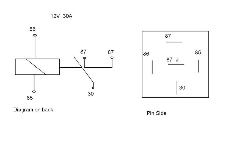
Most relays have five flat-blade terminals protruding from them. Those five connections are labeled numerically to identify each position's function. The No. 30 connection connects directly to a...
Nitrous wiring diagram - Camaro Forums - Chevy Camaro ...
Nitrous Express Relay Wiring Harnesses Only. These relay wiring harnesses from NOS can be used with standard nitrous systems to allow you to make the right connections. NOS relay wiring harnesses have a range of uses, but one main goal--reliability. Don't settle for an inferior product--equip your ride with NOS quality relays.

Digital Delay - Nitrous Boards
CARBURETOR PLATE NITROUS SYSTEMS INSTALLATION INSTRUCTIONS ...

Nitrous Outlet ProMax Relay Panel - ProNitrous.com
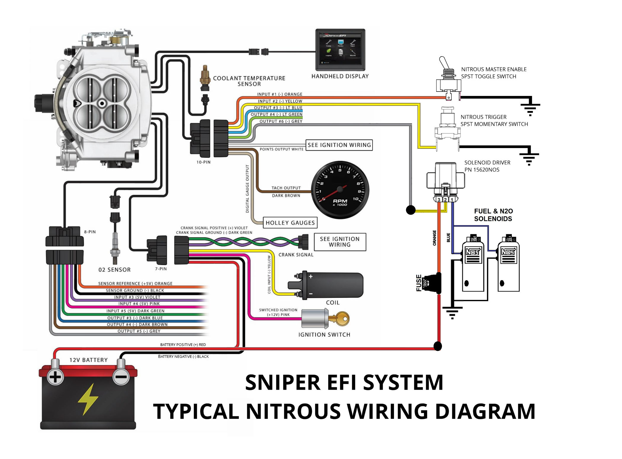
Configuring and Wiring Sniper EFI System for Nitrous Oxide
Nitrous, transbrake and 2 step question - Third Generation F ...

Nitrous install question.. Hobbs Switch... | Nitrous, E85 ...

NOS 30 Amp Relay Assembly
Nitrous Oxide System Installation Help | Cold Fusion Nitrous
need a wiring diagram | Page 4 | Yellow Bullet Forums
NOS 15620NOS Solid State Relay | Ships Free at EFISystemPro.Com

What's the cheapest way to increase horsepower? The answer is ...
Wiring window switch to nitrous kit - LS1TECH - Camaro and ...
S300 plus FJO nitrous controller - Honda-Tech - Honda Forum ...
THROTTLE & RPM-ACTIVATED NITROUS CONTROL SYSTEM
Jegs window switch vs. nos window switch | Modded Mustang Forums

Nawz Wiring! | LS1GTO Forums
0 Response to "38 nos relay wiring diagram"
Post a Comment