37 ag-cu phase diagram
Eutectic Phase Diagram Ag + Cu Univariant Equilibrium Liquidus Solidus Invariant Equilibrium Eutectic Lever Rule Tieline(conode) and Silver acts like a solvent to copper and copper acts like a solvent to silver with limited solubility that is a function of temperature with a solubility limit at the eutectic point (3 phases in equilibrium) 1 Phase diagrams; Equilibria in gases; Some example exercises include: Define the system Co. What phase is most stable at 1 bar and 1000K? Evaluate the molar Gibbs energy of the compound Fe3C at 1000 °C. Calculate the ternary phase diagram W-Co-C at 1 bar and 1400 °C. Perform the calculation by varying the mole percent of Co and C.
Phase Diagram Resources from ASM International. Alloy phase diagrams and crystal structure data are used by metallurgists, materials engineers, and materials scientists to develop new alloys for specific applications; fabricate these alloys into useful configurations; design and control heat treatment procedures for alloys that will produce the required mechanical, physical, and chemical ...
Ag-cu phase diagram
Ag-45 wt% Cu composition at 900 °C. As may be noted, point C lies within the Liquid phase field. Therefore, only the liquid phase is present; its composition is 55 wt% Ag-45 wt% Cu. (d) The Mg-Pb phase diagram (Figure 9.20) is shown below; the point labeled "D" represents the 30 w t% Pb-70 wt% Mg composition at 425 °C. Ag 1100 Eutectic phase diagram for a silver-copper system. 2800 2600 2400 2200 2000 1800 1600 MgO CaO 20 40 60 80 100 0 C) L MgO ss + L MgO ss CaO ss + L CaO ss MgO ss + CaO ss Wt % Eutetic phase diagram for MgO-CaO system. Temperature (Lecture 19 - Binary phase diagrams 4 of 16 11/23/05 PHASE DIAGRAMS PROBLEM SOLUTIONS 9.17 A 90 wt% Ag-10 wt% Cu alloy is heated to a temperature within the β + liquid phase region. If the composition of the liquid phase is 85 wt% Ag, determine: (a) The temperature of the alloy (b) The composition of the β phase (c) The mass fractions of both phases Solution
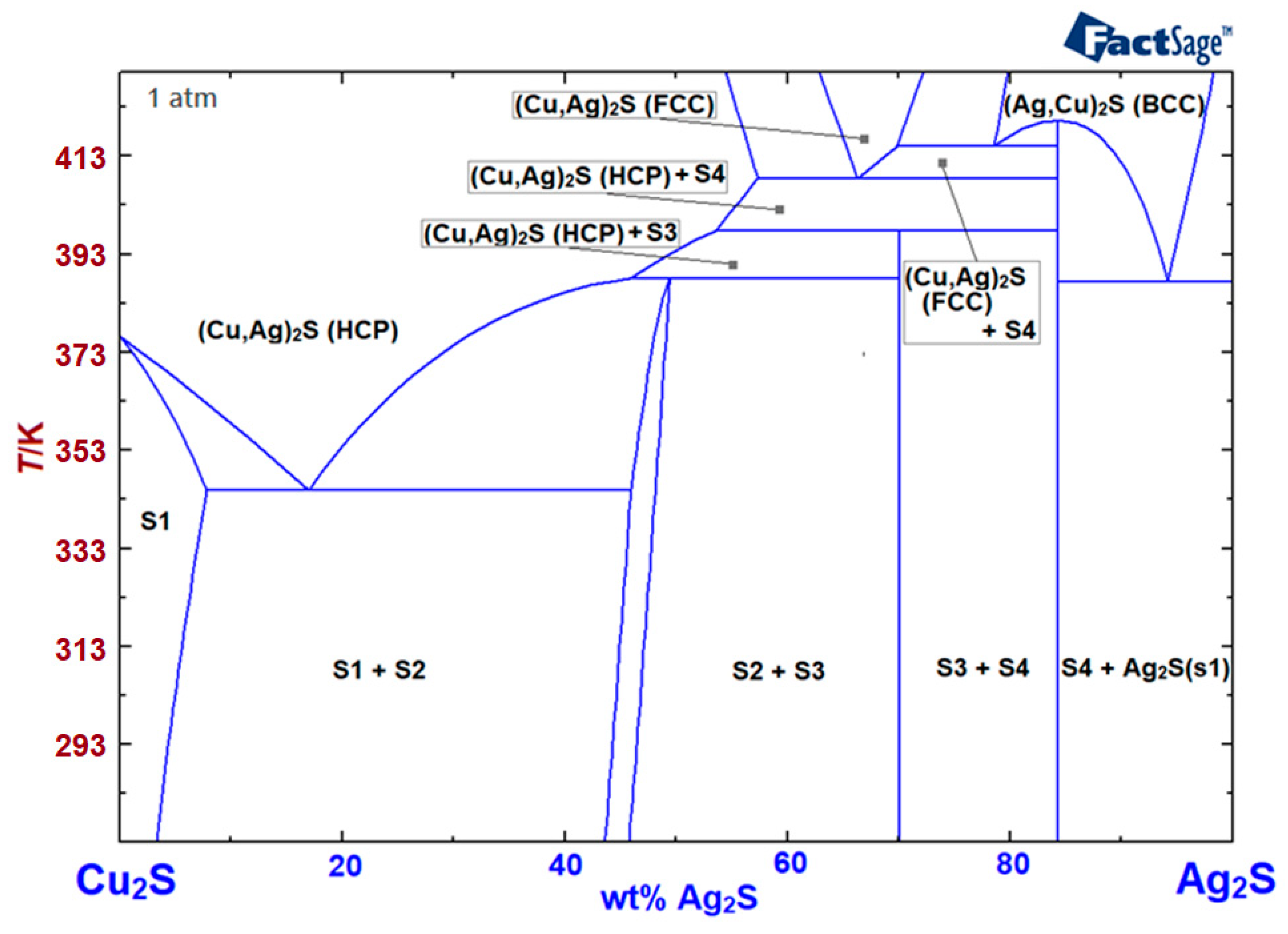
Ag-cu phase diagram. By applying the obtained results and the critically evaluated literature data, we have developed a thermodynamic database. The self-developed database was combined with the latest pure substances database of the FactSage software package to model the phase diagram of the Ag 2 S-Cu 2 S system. Additionally, some compositions represent key regions of the Cu-Ag phase diagram, shown in Figure 9. For example the 30 wt% Cu - 70 wt% Ag alloy is very close to the eutectic composition (28.1 wt%... The phase diagrams of Ag-Cu nanoalloys were thermodynamically re-investigated. • A self-consistent thermodynamic data set including the size effect was obtained. • Four Ag-Cu nano phase diagrams were constructed and compared with experimental data. • The calculated Ag-Cu nano phase diagrams agreed well with experimental data. Abstract This phase diagram consists of two points, two lines and three areas. The two points of the two pure metals A & B. The upper line, obtained by connecting the points showing the beginning of solidification is called liquidius line, and the lower line, determined by connecting the points showing the end of solidification is called the solidus line.
ABSTRACT The Ag-Cu phase diagram at nanoscale was reassessed by CALculation of PHAse Diagrams (CALPHAD) method, considering the surface effect on the chemical potential of pure substance and excess Gibbs free energy of mixtures. J. Markali and P. Thoresen,"The Ag-Rich Side of the Binary Phase Diagrams Ag/Au and Ag/Cu as Studied by Zone Refining,"Acta Chem. Scand, 15,31-35 (1961). (Equi Diagram; Experimental) Article Google Scholar 62Dob: Jan 09, 2022 · EDS quantification result of samples I and II, phase diagram of the Au–Ag–Cu system, low-loss EELS spectra from nanoparticles of samples I and II, structures of L1 0 and L1 2, EDS compositional analysis of sample I, EDS spectrum of phase-separated L1 2 and FCC in sample II, EDS compositional analysis of sample II, detailed filtering process ... Transcribed image text: Q4 Draw the fullibrium Phase diagram of the binary alloy (Ag-CU) from the following data :- copper Meltingat lo83 c. silver melting at 961 Ć eutectic mixture consists of (76% Ag -30% cu) at 780°c that the maximum solubility of copper in silver is gwt% at 780°C but the maximum solubility of silver in copper 8 wt% at 780°C. and the solubility limits to each others ...
FactSage 8.1 - List of Stored Phase Diagrams (7811) FACT Databases. FToxid FACT oxide data (501) FTsalt salt data (351) FTmisc sulfide, alloy, micellaneous data (39) ... Ag-Cu BINS: Ag-Cu FScopp: Ag-Cu FSlead: Ag-Cu FTlite: Ag-Cu SGnobl: Ag-Cu SGsold: Ag-Cu SGTE 2014: Ag-Cu SGTE 2017: Ag-Cu SGTE 2020: Ag-Cu-Fe_1550C SGnobl: i.e. is the crystal structure of a hypothetical γ″ phase in iron the same as in manganese? Or might one be BCC and the other HCP? New to metallurgy https://imgur.com/a/x8XS0si What's the striped line? And what's up with the L (liquid) and glass? Something can't be glass and liquid simultaneously. Phase equilibria in the Ag-CuO-Cu 2 O system were experimentally determined using thermal analysis, and structural and compositional studies. Three reactions were observed in air: (1) L 1 = CuO + Ag, (2) L 2 = CuO + L 1, and (3) Cu 2 O = CuO + L 2.The evolution and absorption of oxygen accompanied these reactions.
Chapter 9. Phase Diagrams
MSI Eureka - is the world‘s leading interactive database for high-quality evaluated phase diagrams and related constitutional data. It provides information on all inorganic materials. It provides outstanding basic scientific information for research and development in the field of materials science, metallurgy, chemistry, physics, engineering ...

File:Sn-Ag-Cu-phase-diagram-greek.svg - Wikimedia Commons
Phase Diagrams & Computational Thermodynamics. Ag-Cu-Sn System. Calculated Liquidus Projection: Sn-rich Part: Status of the thermodynamic description: Ternary liquid adjusted to reproduce the eutectic L ->Ag 3 Sn + Cu 6 Sn 5 + (Sn) U.R. Kattner, NIST, 2000 . Sources of the binary descriptions:

Understanding Phase Diagrams MET346 Purdue College of Technology New Albany
(c) The Ag-Cu phase diagram (Figure 9.7) is shown below; the point labeled "C" represents the 55 wt% Ag-45 wt% Cu composition at 900°C. As may be noted, point C lies within the Liquid phase field.

Figure 7 from Precipitation hardening in a dental low-gold ...
Calculated phase diagram of Ag – Cu nanoparticles with r = 10 nm and r = 2 nm together with the bulk Ag – Cu phase diagram are shown in Fig. 3. The results show that by decreasing the particle radius, solidus and liquidus lines shifted to lower temperatures.

Based on the Cu-Ag phase diagram given above, which of the ...
Janet, The areas on the right and left of that diagram represent the single phase solid areas in the Ag Cu system. What that means is at the ratios and temperatures shown the alloy formed is a single phase solid solution. The reading of phase diagrams is a fairly complex subject and is not one to be condensed to a single email response
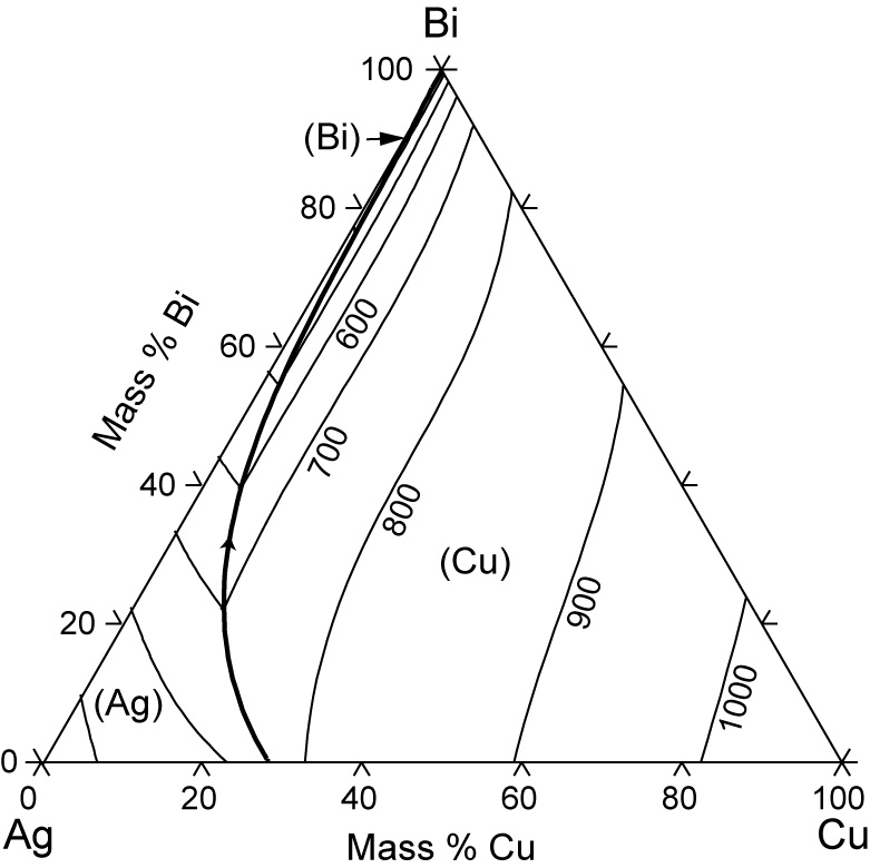
Ag-Bi-Cu Phase Diagram & Computational Thermodynamics
An alloy containing 20x10 \^ 21 atoms of Ag and 73x10 \^ 21 Cu atoms is heated to 780 ° C. Determine (Consider that for Cu and Ag, the specific mass is 8.96 g / cm³ and 10.49 g / cm³ and the atomic weight 63.546 g / mol and 107.8682 g / mol, respectively.) a) The phase (s) present. b) The weight percentage of each phase. https://preview.redd.it/fae3yorsxh461.png?width=664&format=png&auto=webp&s=a3127937f53981e4851da62dc264f65429cdd342
Teach Yourself Phase Diagrams and Phase Transformations
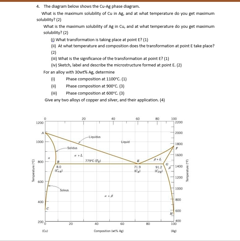
The Ag-Cu phase diagram is given in the figure below. According to this phase diagram, what is: The melting temperature of pure Ag The melting temperature of pure Cu The maximum solubility of Cu in Ag@ 5009C The maximum solubility of Ag in Cu at 600°C The eutectic composition The eutectic temperature The phase rich in Cu The phase rich in Ag
SOLVED:The diagram below shows the Cu-Ag phase diagram. What ...
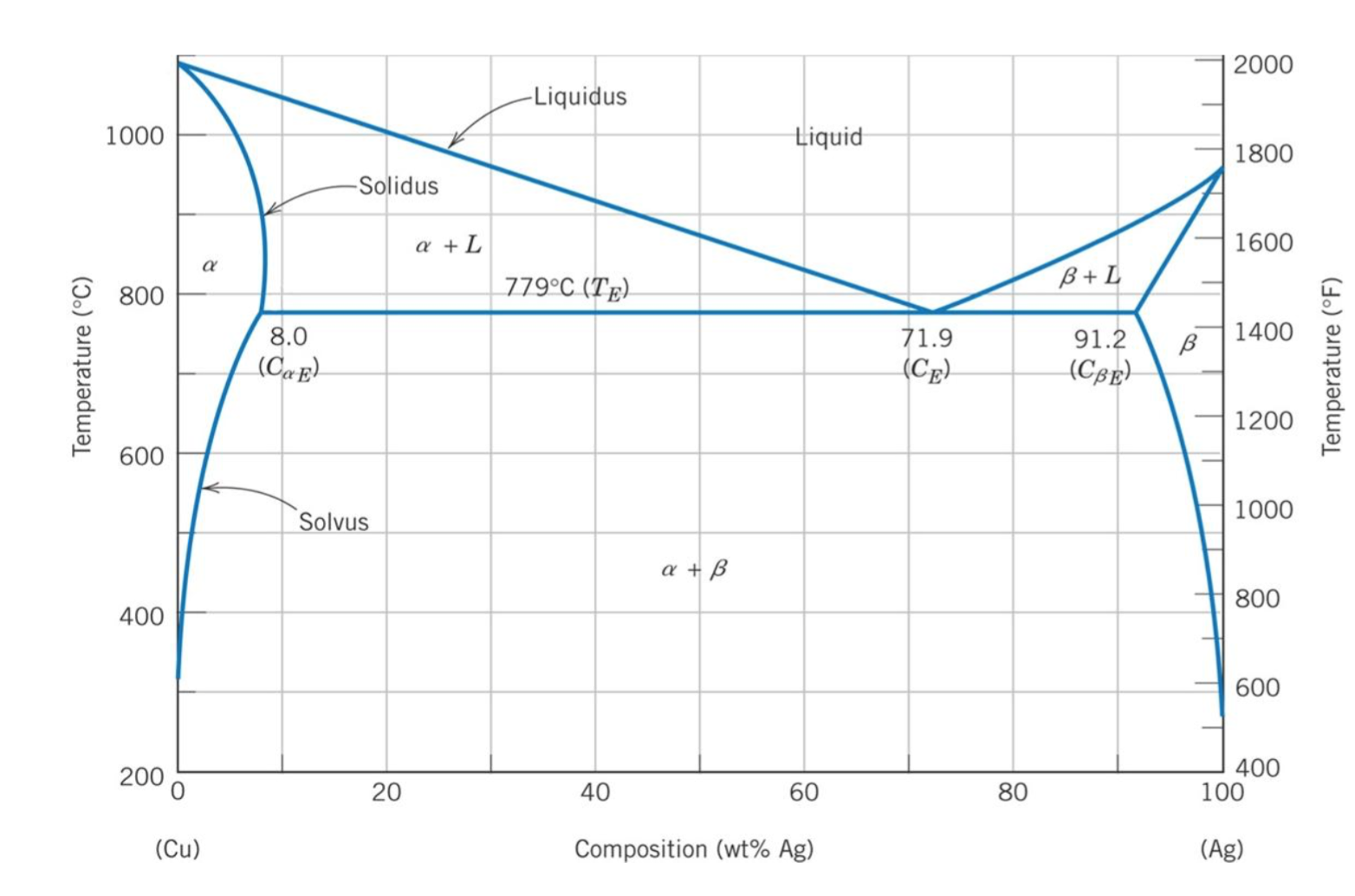
MSE 2090: Introduction to Materials Science Chapter 9, Phase Diagrams 23 Binary Eutectic Systems (II) Three single phase regions (α- solid solution of Ag in Cu matrix, β= solid solution of Cu in Ag matrix, L - liquid) Three two-phase regions (α+ L, β+L, α+β) Solvus line separates one solid solution from a mixture of solid solutions.
Energies | Free Full-Text | Thermal Analysis and Optimization ...
The Cu-Ag equilibrium phase diagram is presented in Figure 1a [20]. The vertical line shows the chemical composition of the examined alloy, while the dots show the annealing temperatures, i.e., 400, 500 and 600 °C.

Ag-Cu Phase Diagram & Computational Thermodynamics ...
Dec 31, 2021 · Chen et al. brazed CoSb 3 base SKD with Ag Cu filler. Prior to brazing process, Co barrier layers were prepared on the surface of SKD. ... Schematic diagram of the contact resistivity tests. 3 ... The Spot 3 was the Mo-rich phase of the HEAs and the chemical composition of Spot 4 was corresponding to the Mo-poor phase/p-SKD interfacial reaction ...

Thermodynamic modeling of Ag – Cu nanoalloy phase diagram ...
Figure 3 and 4 presents the calculated Ag-Cu-Ti phase diagram, along with experimen-tal data points obtained from the literature (See [17, 14]). In general, the agreement is. quite good.
![Solved] Consider the Cu-Ag phase diagram provided. What ...](https://s3.amazonaws.com/si.experts.images/questions/2020/04/5ea766ffc163d_0ZZXBS6DM9XYDCBG15H.png)
Solved] Consider the Cu-Ag phase diagram provided. What ...
I’d like to wire one of my guitars with 2 humbuckers with a volume and tone for each, a 3 way pickup selector switch, a 2 way switch to go out of phase, and a 2 way switch to split the coils. Like the wiring on the frank zappa Roxy SG.
Self-Assessment: Solid Solutions 800 600 600 400 400 α+β α β ...
be noted in the Ag-Cu phase diagram shown below (at point C)—i.e., WL = 1.0 . Excerpts from this work may be reproduced by instructors for distribution on a not-for-profit basis for testing or instructional purposes only to students enrolled in courses for …

Ag-Cu phase diagram. 4) | Download Scientific Diagram
Download scientific diagram | Phase diagram of Cu-Ag from publication: Fabrication, properties and microstructures of high strength and high conductivity copper-silver wires | Research results of ...
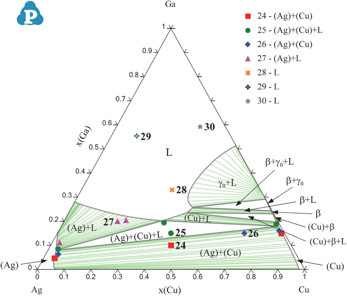
Experimental Investigations of Phase Equilibria in Ternary Ag ...
[2 marks] (c) You are given an alloy of Ag-Cu at 20 wt% for a high temperature application. By drawing on the diagram, and showing your working: (i) Find the minimum temperature required to completely melt the alloy.[1 mark] (ii) Calculate the % liquid in the alloy at 900°C.

Using the Ag-cu phase diagram, calculate the weight of solid ...
Phase Diagrams • Indicate phases as function of T, Co, and P. • For this course:-binary systems: just 2 components.-independent variables: T and Co (P = 1 atm is almost always used). • Phase Diagram for Cu-Ni system Adapted from Fig. 9.3(a), Callister 7e. (Fig. 9.3(a) is adapted from Phase Diagrams of Binary Nickel Alloys , P. Nash
Phase Diagrams | Shuanglin Chen
Use the following silver-copper phase diagram for Problems 5-9. 5. What are the solubility limits of Ag in (Cu) and Cu in (Ag)? Recall that (Cu) and (Ag) are the same as α and β, respectively. The solubility limit of Ag in (Cu) is 7.9 wt. % Ag. The solubility limit of Cu in (Ag) is 8.8 wt.% Cu. Note that these
Experimental Investigations of Phase Equilibria in Ternary Ag ...
Phase Diagram. このサイトを検索 ... Ag-Cu. Data from RICT-Sol alloy database ver.1.0. Sign in | Recent Site Activity | Report Abuse | Print Page | Powered By Google Sites ...
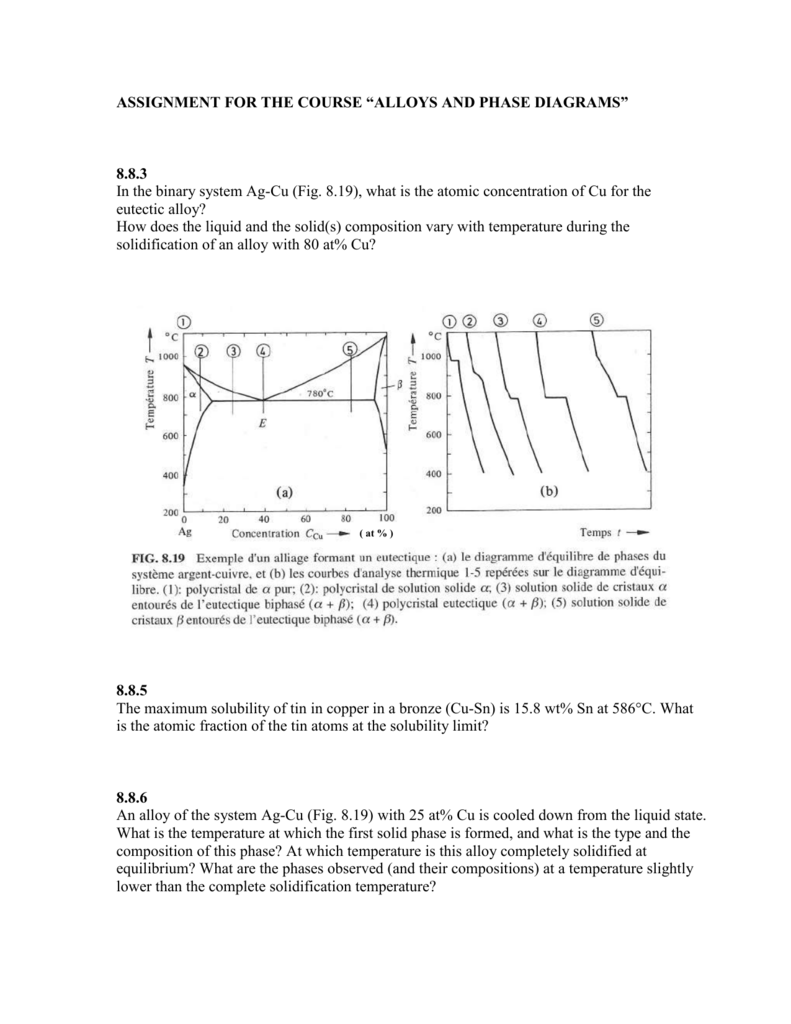
Assignment-chap8
Ag-Cu-Mn Liquidus Projection of Ternary Phase Diagram ... Phase diagram available to subscribers; If you are having trouble in accessing SpringerMaterials remotely during the COVID-19 pandemic, Get help with remote access; To view content, please Log in, ...
Phase transformations in Ag70.5Cu26.5Ti3 filler alloy during ...
It showed all their developmental products

File:Diagramme phase Ag-Cu.jpg - Wikimedia Commons
Ag-Au-Cu-phase-diagram-greek.svg. Phase diagram ( liquidus curves) for Ag-Au-Cu alloys. Such alloys are very common in jewelery production. Legends in Greek. Date. 17 November 2007. Source. Self-made with data from: H. Baker et al. (editors), ASM Handbook, vol. 3, Alloy Phase Diagrams. ASM International, Materials Park, Ohio, USA, 1992.

Consider the Cu-Ag phase diagram in figure below. At a ...
Status of the thermodynamic description: F.H. Hayes, H.L. Lukas, G. Effenberg and G. Petzow, Z. Metallkde. 77 (1986) 749-754: Full thermodynamic assessment, adapted ...
HOMEWORK 6.
Ag Cu Phase Diagram. Here are a number of highest rated Ag Cu Phase Diagram pictures on internet. We identified it from well-behaved source. Its submitted by management in the best field. We give a positive response this kind of Ag Cu Phase Diagram graphic could possibly be the most trending subject in imitation of we share it in google pro or ...
Eutectic Systems
Melting temperatures of Sn-Ag-Cu (SAC) alloys in the Sn-rich corner are of interest for lead-free soldering. At the same time, nanoparticle solders with depressed melting temperatures close to the Sn-Pb eutectic temperature have received increasing attention. Recently, the phase stability of nanopar …
Solved Problem 2 (0.5 pt max). The copper-silver (Cu-Ag ...
Ch. 14: Potentiometry Outline: • 14-1 Reference Electrodes • 14-2 Indicator Electrodes • 14-3 What is a Junction Potential? • 14-4 How Ion-Selective Electrodes Work • 14-5 pH Measurement with a Glass Electrode • 14-6 Ion Selective Electrodes Updated Nov. 30, 2011, slides 1 and 23
homework 5 solutions
Phoenix Gold Begins Phase 2 Drilling at York Harbour Cu-Zn-Ag-Co Project in Newfoundland The Phase 1 drilling program successfully validated historical drilling results. The Phase 2 program will include both delineation & exploration drilling #batterymetals #copper #trading #exploration https://www.nxtmine.com/news/articles/base-metals/copper/tsxv-pxa-phoenix-gold-begins-phase-2-drilling-at-york-harbour-copper-zinc-silver-cobalt-project-newfoundland/

1 picture- problem 2 other pictures- phase diagrams fo ...
Phase diagram of Ag - Cu question Thread starter vigintitres; Start date Jun 25, 2009; Jun 25, 2009 #1 vigintitres. 26 0. Homework Statement Describe equilibrium cooling from 1200 C to 200 C of an alloy containing 40 wt% Ag. Draw the schematic equilibrium cooling curve The Attempt at a Solution

ag-cu - atdinsdale
PHASE DIAGRAMS PROBLEM SOLUTIONS 9.17 A 90 wt% Ag-10 wt% Cu alloy is heated to a temperature within the β + liquid phase region. If the composition of the liquid phase is 85 wt% Ag, determine: (a) The temperature of the alloy (b) The composition of the β phase (c) The mass fractions of both phases Solution
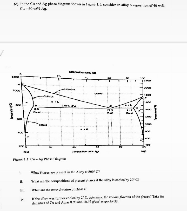
Answered: Figure 1.1: Cu - Ag Phase Diagram i.… | bartleby
Ag 1100 Eutectic phase diagram for a silver-copper system. 2800 2600 2400 2200 2000 1800 1600 MgO CaO 20 40 60 80 100 0 C) L MgO ss + L MgO ss CaO ss + L CaO ss MgO ss + CaO ss Wt % Eutetic phase diagram for MgO-CaO system. Temperature (Lecture 19 - Binary phase diagrams 4 of 16 11/23/05

Cu-Ag Phase Diagram. The eutectic composition is 28.1 wt% Cu ...
Ag-45 wt% Cu composition at 900 °C. As may be noted, point C lies within the Liquid phase field. Therefore, only the liquid phase is present; its composition is 55 wt% Ag-45 wt% Cu. (d) The Mg-Pb phase diagram (Figure 9.20) is shown below; the point labeled "D" represents the 30 w t% Pb-70 wt% Mg composition at 425 °C.

Figure 1 | The Effects of Adding Elements of Zinc and ...
Ternary Eutectic Alloy - Basics - Phase Field Models of ...

Binary eutectic phase diagram of the Ag-Cu system (based on ...
14: Silver Amalgam | Pocket Dentistry

Figure 15 | Ag-Cu Colloid Synthesis: Bimetallic Nanoparticle ...
![Solved] Consider the Cu-Ag phase diagram provided. What is ...](https://s3.amazonaws.com/si.experts.images/questions/2020/04/5ea7663ae13cb_OFJ6VCKE4R7C6L.png)
Solved] Consider the Cu-Ag phase diagram provided. What is ...

Using the Ag-cu phase diagram, calculate the weight of solid ...
0 Response to "37 ag-cu phase diagram"
Post a Comment