42 hand off auto wiring diagram
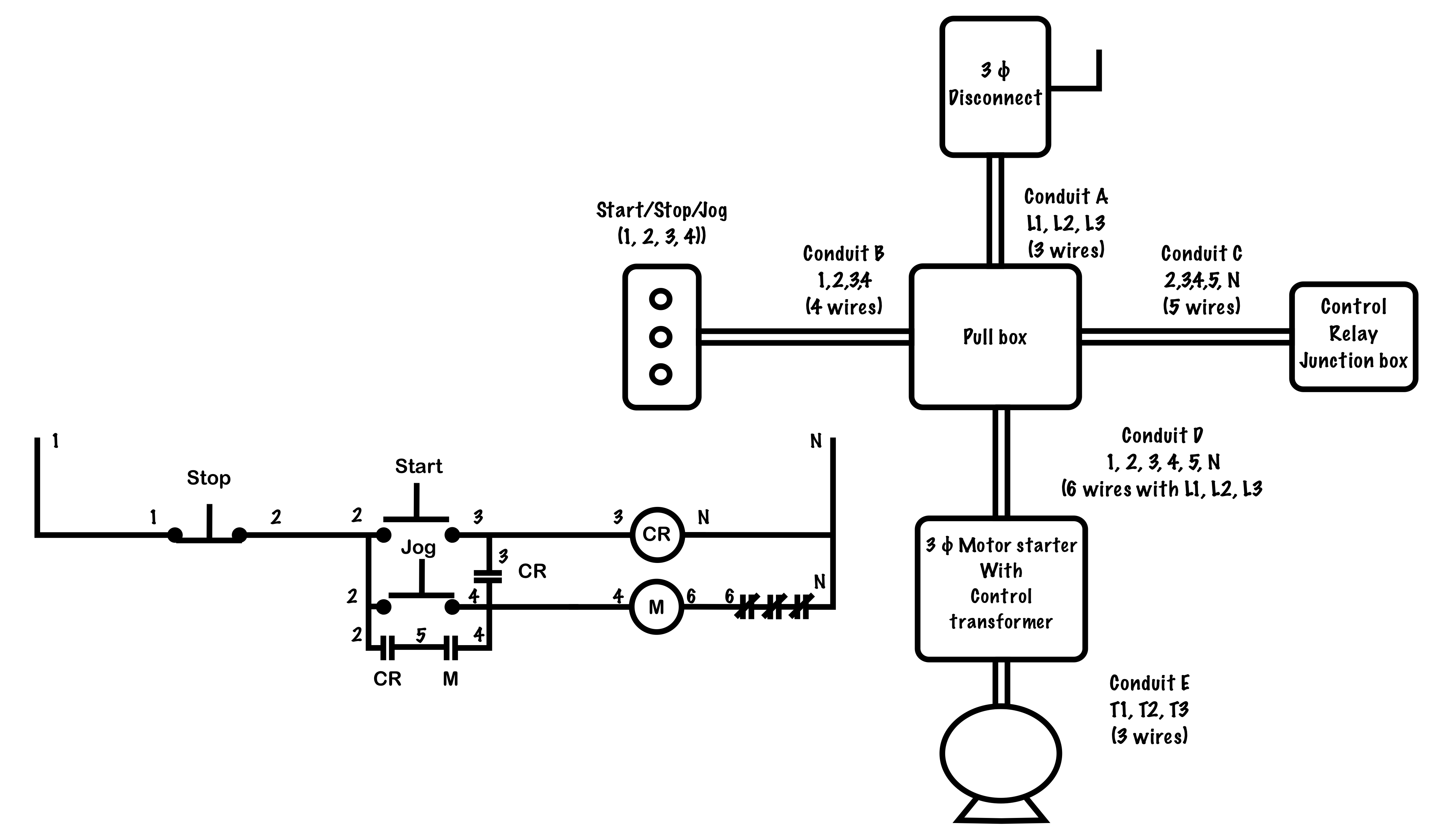
Wiring diagrams, sometimes called “main” or “construc-tion” diagrams, show the actual connection points for the wires to the components and terminals of the controller. They show the relative location of the components. They can be used as a guide when wiring the controller. Figure 1 is a typical wiring diagram for a three-phase mag- There are many different ways to look at fixing an electrical problem but we will stick with the easiest way. First , find the problem area on the wiring diagram. Highlight the individual circuit using a different color for positive and negative. Trace the wiring till you can see where a short may have taken place.
Basics 7 4.16 kV 3-Line Diagram : Basics 8 AOV Elementary & Block Diagram : Basics 9 4.16 kV Pump Schematic : Basics 10 480 V Pump Schematic : Basics 11 MOV Schematic (with Block included) Basics 12 12-/208 VAC Panel Diagram : Basics 13 Valve Limit Switch Legend : Basics 14 AOV Schematic (with Block included) Basics 15 Wiring (or Connection ...

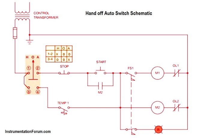
Hand off auto wiring diagram
Incoming wire size range of non-fused disconnect with MCA from 600 to 799.9 amps is 1/0 to 500 kcmil. Incoming wire size range of non-fused disconnect with MCA from 800 to 1199.9 amps is 250 to 500 kcmil. 3. Terminals 9 and 10 of TB5 are for field exte rnal connections for remote on-off. The contacts must be rated for dry circuit ap pli- May 01, 2017 · Hand Off Auto HOA controls are a very common and versatile control circuit which allows both automatic and manual operation. It allows loads such as motors, solenoid valves, electric cylinders, etc. to be controlled by some automatic operation such as a sensor or PLC plus allows you to easily turn the load on manually or off manually. Hand Off Auto Wiring Diagram from static-resources.imageservice.cloud. Print the electrical wiring diagram off and use highlighters to trace the signal. When you employ your finger or follow the circuit together with your eyes, it’s easy to mistrace the circuit. One trick that I use is to print out the same wiring diagram off twice.
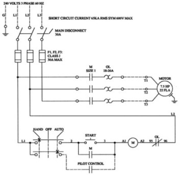
Hand off auto wiring diagram. Wiring Schematics Standard product wiring diagram shown. As-built product wiring may vary. Product wiring diagram located on starter enclosure. H1 H4 L1 L2 L3 MTR T1 T3 AUX CONT M T2 OL 3PH 43 44 31 32 A1 A2 M Control Limit Switch Normally Open Input Actuator Control 24VDC, 1A Output Dry Inputs Relay Outputs Common Fault Status Fireman's Override 12-250VAC/DC Input Auto Run • Often a hand-drawn diagram of a control circuit con-structed in the field helps in understanding how a circuit functions and how to make the necessary connections, especially during the learning process. Figure 1-9 shows the hand-drawn version of the 3-wire start-stop control circuit shown in Figure 1-3. Notice that the stop 2. Install the orange wire from the Main Speed Potentiometer assembly (removed in step 1) to the top terminal of the Auto/Manual Switch assembly. See figure 3. 3. Install the blue wire from the center of the Auto/Manual Switch assembly to the SIG terminal on the KBRC-240D PC board. See figure 3. 4. Install the green wire from the SIRC CON1 to ... These are the wiring diagrams for lighting and heating contactors. 20A CLM Lighting Contactor Typical Photocell 2W Acc · 20A CLM Lighting Contactor. The proper voltage rated photocell must be used or damage will occur. Refer to the Lighting Control Contactor wire diagram for the specific photocell voltage.
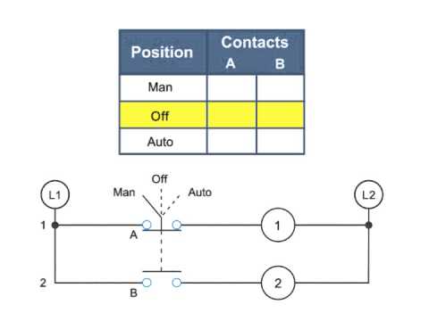
When the driver turns the ignition key to the "start" position, the solenoid engages a plunger, which, in turn, acts on a lever fork inside of the starter. The fork then pushes the starter's pinion gear into mesh with the ring gear on the engine's flywheel or flexplate. Also, the solenoid's plunger pushes a disc against a set of contacts. Choose from our selection of hand off auto switches, including metal 30 mm panel-mount lever switches, 16 mm panel-mount lever switches, and more. In stock and ready to ship. In this lesson we'll examine a common industrial application of 2 wire control circuits known as a HAND-OFF-AUTO circuit. We’ll discuss the devices that make... ‘Off’ position. The ‘Auto’ position allows the motor to turn on and off according to some programmed automatic cycle. Corsair offers a ‘H-O-A’ device type that provides a computer equivalent to a ‘Hand-Off-Automatic’ panel switch. It allows the operator to force an item on, force it off or let it operate automatically.
In the Reference Manual and shown below is a wiring diagram and parameter settings that will work for a 22-Series I/O Module catalog number 20-750-2262C-2R (24 Volts DC). The example is good for this optional I/O card. If you would like the manual reference to come from a source other than the source commanding manual control Hand Off Auto Selector Switch Wiring Diagram – One of the most hard automotive repair tasks that a mechanic or fix shop can take is the wiring, or rewiring of a car’s electrical system. The hardship in fact is that all car is different. considering bothersome to remove, replace or repair the wiring in an automobile, having an accurate and detailed hand off auto selector switch wiring diagram is vital to the finishing of the repair job. WIRING DIAGRAMS m c w Bulletin 600 Bulletin 600 manual starting switches are designed for starting and protecting small AC and DC motors rated at 1 HP or less where undervoltage protection is not needed. They are operated by a toggle lever mounted on the front of the switch. Wiring diagrams do not show the PDF Automotive Wiring Diagrams. The standard labeling system will use the first letter to indicate the base color, and the second letter to indicate the stripe color. An example would be the letters OB. This represents an orange colored wire with a black tracer stripe. RB is red with a black tracer.
Practical Machinist - Largest Manufacturing Technology Forum ...
Hand Off Auto HOA controls are a very common and versatile control circuit. It allows loads such as motors, solenoid valves, electric cylinders, etc. to be ...
Timeline 32
Typical Wiring Diagrams For Push Button Control Stations 7 Start-Stop Control Wiring Diagrams SINGLE STATION -WITH MOTOR STOPPED PILOT LIGHT L1-_ START L2 I 1 STOP 2 OI" 3 n w..O.L. --c I m N.C. Aux. ' 't\ w 6. PILOT LIGHT L2 4 2 3 PILOT LIGHT START STOP Bulletin 1495 normally closed auxiliary contacts are required.

SW182 Type Motor Reversing DC Contactor
HZ owners wiring help. Finally have the Monaro in the new shed and want to wire it up, I have the HQ and HZ wiring diagrams and have identified most of the connectors but still have a few to go. I have an HZ Statesman loom with GTS dash, A/C, HQ body harness and an efi 5ltr so it is a little more complicated than normal, plus I haven't had the ...

Float Switch Installation Wiring & Control Diagrams | APG
Jun 08, 2021 · Square D Hand Off Auto Switch Wiring Diagram – Hello friends Electrical Wiring In the article you are reading this time with the title Square D Hand Off Auto Switch Wiring Diagram we have prepared this article well so that you can read and retrieve the information in itHopefully the content of the post Article square d hand-off-auto switch ...
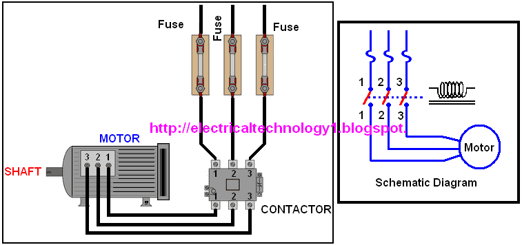
A Simple Circuit Diagram of Contactor with Three Phase Motor
A car wiring diagram is a map. To read it, identify the circuit in question and starting at its power source, follow it to the ground. Use the legend to understand what each symbol on the circuit means. I'm an auto technician for over twenty years, I've always loved the electrical side of auto repair.
HAND-OFF-AUTO Circuits (Full Lecture) - YouTube
Wiring Diagram Book A1 15 B1 B2 16 18 B3 A2 B1 B3 15 Supply voltage 16 18 L M H 2 Levels B2 L1 F U 1 460 V F U 2 L2 L3 GND H1 H3 H2 H4 F U 3 X1A F U 4 F U 5 X2A R Power On Optional X1 X2115 V 230 V H1 H3 H2 H4 Optional Connection Electrostatically Shielded Transformer F U 6 OFF ON M L1 L2 1 2 STOP OL M START 3 START START FIBER OPTIC ...
PHOTOCELL w/ Magnetic Contactor Wiring and diagram for Street ...
Lights To Photocell Contactor Wiring Diagram - Wiring Diagram Volvo V70 Ceiling Fan Light Switch Wiring Diagram Wiring Diagram For Amp Meter Jeep Grand Cherokee Transmission Wiring Diagram. View and Download MFZ Ovitor E6L user manual online. Apr 07, · From /V panelboard, I have a V feed to a 3 way switch (auto, ON and OFF) which controls the photocell and timeclock (both are connected in parallel) which then control the contactor.

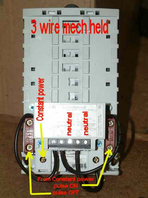
GRay again. What would make a mechanically held latch and ...
Wiring For 2 Hoa Stations Electrician Talk. The Purpose Of This Assignment Is To Observe Operation Chegg Com. Eaton Selector Switch Kit Hand Off Auto 00 To 5 Starter Size Black White 1 12 3r 4x Nema Rating 6vlf4 C400t12 Grainger. Hand off automatic controls basic auto switch operation symbols electric motors generators selector switches diagram ...
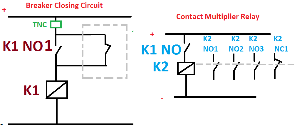
Contact Multiplier Relay Working Function & Wiring diagram ...
with Hand-Auto HAND - TOGGLE CLOSED AUTO - TOGGLE OPEN AUTO HAND 115-230V 1HP / 230V L1 L2 T1 T2 MS R PILOT LIGHT (IF USED) MOTOR THERMOSTAT Figure 6. Wiring Diagram Figure 5. Terminal Access Access terminals by loosening screws on top of the starter TABLE 1. MST HEATER PACK TABLE (Wire with 60°C / 70°C wire) Code Marking Full-Load Current of Motor (Amps)
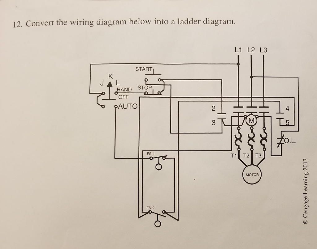
Solved 12. Convert the wiring diagram below into a ladder ...
Hand Off Auto Wiring Diagram. Hand Off Auto Wiring Diagram from static-resources.imageservice.cloud. To properly read a wiring diagram, one has to find out how the components inside the program operate. For instance , in case a module is powered up and it sends out the signal of 50 percent the voltage in addition to the technician will not know this, he'd think he has a challenge, as this individual would expect a 12V signal.

Contactor holding circuit with Push Button Switch - ETechnoG
Standard Diagrams Transfer between 2 sources - 2 Bus bars First type of architecture : S1 (kVA) > SG (kVA) COMUT 044 A T1 NCL Q1 CL Q2 ATS G COMUT 043 A G NCL P1 P3 CL P2 Standard solution SOCOMEC solution Operating table T1 G STD SOCOMEC NCL CL 0 0 X X Off Off 0 1 P2 Q2 Off On 1 0 P1 + P3 Q1 On On
Any help on trying to figure out this diagram? Boss gave it ...
Contactor Wiring Diagram For 3 Phase Motor with Overload relay. In the industrial system, we use mostly three phases of electric power for electric ...
Selector Switches and Contacts in a Diagram - What They Do
Hand OFF Auto Black 3/14 Red 1 Hand Auto Red 1 Yellow - to Coil A1 Terminal Black 3/14 Start Stop Black 3/14 Red 1 Yellow 2/13 Local Control Options (If Used) Refer to Diagram Inside Enclosure for Connections Figure A START/STOP Pushbutton S.P.S.T. Switch Figure B 2-Position Selector Switch S.P.S.T. Switch Figure C 3-Position Selector Switch S.P.S.T. Switch Remove Lead from

Motors, Disconnects, Drives, and Controls, Oh My! | 2021-03 ...
Hand Off Auto Wiring Diagram from static-resources.imageservice.cloud. Print the electrical wiring diagram off and use highlighters to trace the signal. When you employ your finger or follow the circuit together with your eyes, it’s easy to mistrace the circuit. One trick that I use is to print out the same wiring diagram off twice.

Wiring Diagram Double Check | Homebrew Talk - Beer, Wine ...
May 01, 2017 · Hand Off Auto HOA controls are a very common and versatile control circuit which allows both automatic and manual operation. It allows loads such as motors, solenoid valves, electric cylinders, etc. to be controlled by some automatic operation such as a sensor or PLC plus allows you to easily turn the load on manually or off manually.

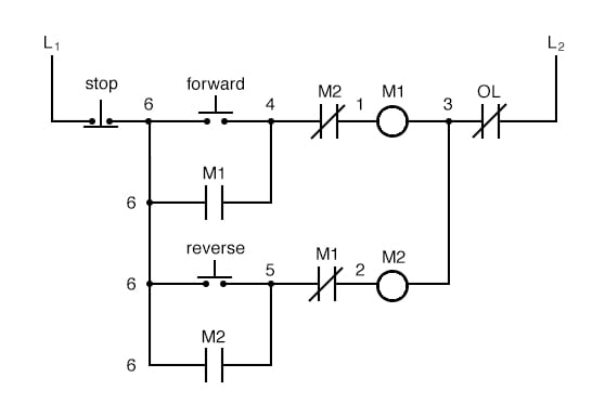
45 Unique Reversing Motor Starter Wiring Diagram | Electrical ...
Incoming wire size range of non-fused disconnect with MCA from 600 to 799.9 amps is 1/0 to 500 kcmil. Incoming wire size range of non-fused disconnect with MCA from 800 to 1199.9 amps is 250 to 500 kcmil. 3. Terminals 9 and 10 of TB5 are for field exte rnal connections for remote on-off. The contacts must be rated for dry circuit ap pli-
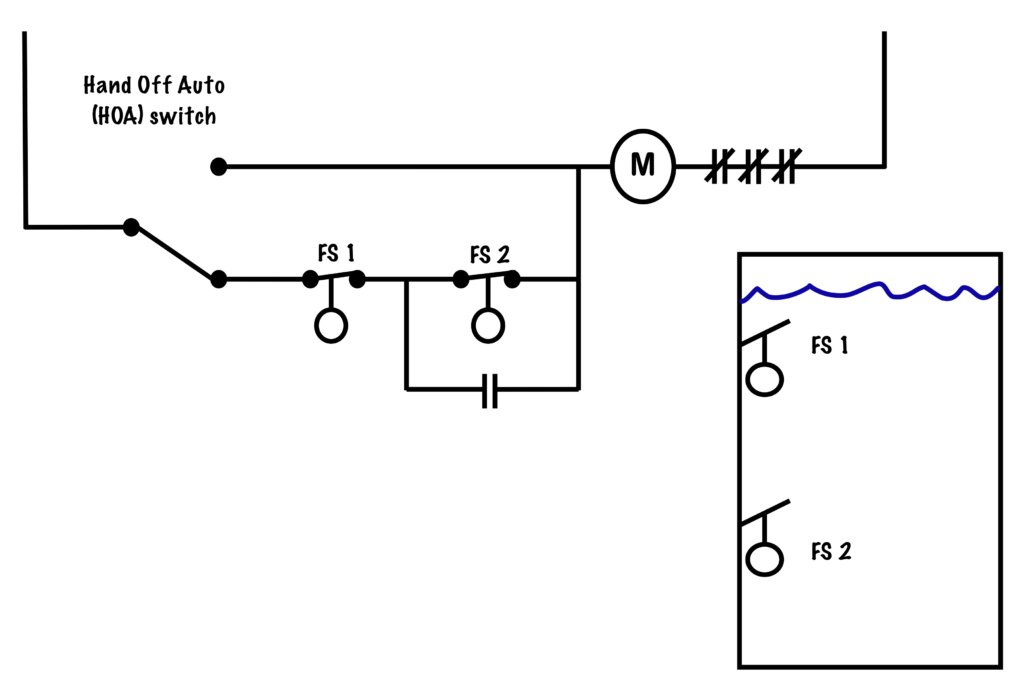
Reservoir Circuit – Basic Motor Control

Motor Starter Wiring Diagrams - VintageMachinery.org ...
FAQ EMSCO, Motor Control Shop, motor starter FAQ

Wiring Diagram Basics for Android - APK Download

How to Construct Wiring Diagrams | Industrial Controls

Pictures on how to wire a contactor? - Answers

Eaton/Moeller DILM32-10 3 Pole IEC Contactor | Kent Industries

How to wire a HOA Hand Off Auto Control Circuit

Hand-Off Automatic Controls (Basic Control Circuits)
IF 1698 - XLC Explosionproof Lighting Contactors
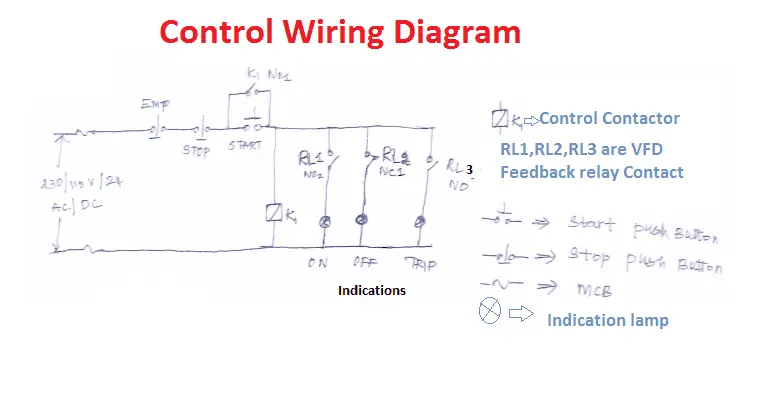
VFD Start Stop Wiring Diagram | Electrical4u

Motor Starter Wiring Diagrams - VintageMachinery.org ...
Selector Switches | Diagram, Video and Selector Switch ...

Electrical Contactor Connection and Wiring Diagram - ETechnoG

FAQ EMSCO, Motor Control Shop, motor starter FAQ
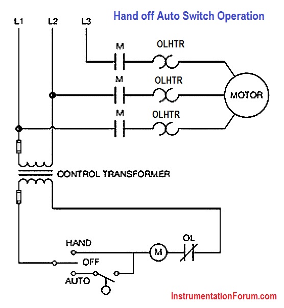
Hand off Auto Switch Operation - Electrical Engineering ...
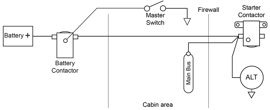
Aircraft Wiring
Superior Panels - NEMA 3R Standard Pump Panels

Hager ESC 125 Contactor switch wiring - Web Design & SEO Company
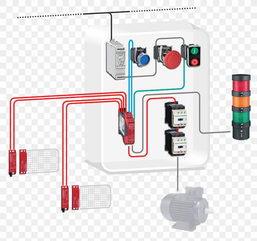
Contactor Schneider Electric Wiring Diagram Safety Machinery ...

Electrical Contactor Connection and Wiring Diagram - ETechnoG
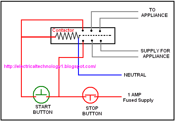
Working of contactor: A simple circuit diagram
Motor Control Circuits | Ladder Logic | Electronics Textbook
Wiring of a contactor LC1D091o to a daynight switch | DIY ...

Contactors

Pro-160 / 360 Failsafe Contactor - 4QD - Electric Motor Control
0 Response to "42 hand off auto wiring diagram"
Post a Comment