40 free body diagram of a pendulum
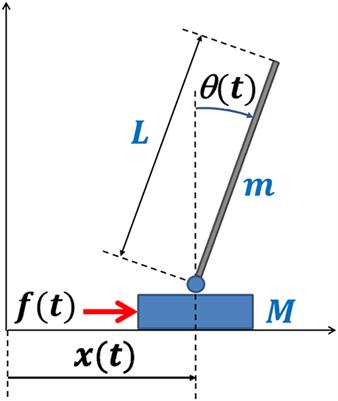
You must enable JavaScript in order to use this site of the inverted pendulum-cart system. In (1), F a is the force exerted on the cart by the motor. (M+ m) x+ mL p = F a (1) mL p x + 4mL2 p 3 mgL p = 0 (2) One way of doing this is by considering the free-body diagrams of the cart and the pendulum separately and writing their respective equations of motion.
... cart mounted motor driven inverted pendulum free body diagram is shown in Fig. 1 [1-4, 16-18, 20-23]. For this nonlinear system, the equations of the dynamics are developed following the...

Free body diagram of a pendulum
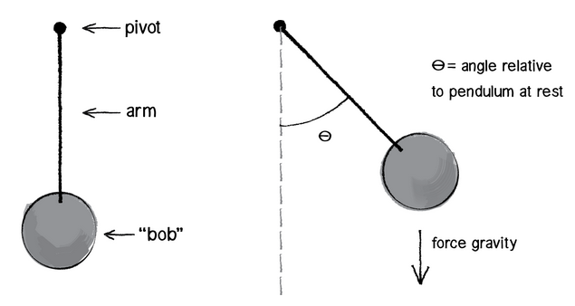
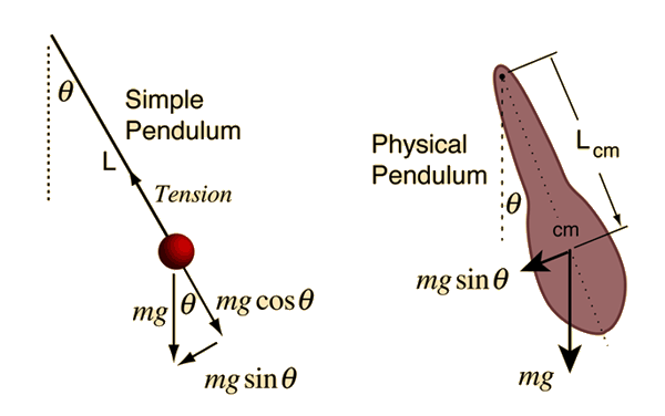
Check here to show the free-body diagram Purple is the true motion; orange is the comparison motion. This is a simulation of a simple pendulum (a ball attached to a massless rod). If the damping is set to zero, the pendulum moves without resistance. The larger the damping, the larger the resistive torque. Single and Double plane pendulum Gabriela Gonz´alez 1 Introduction We will write down equations of motion for a single and a double plane pendulum, following Newton's equations, and using Lagrange's equations. Figure 1: A simple plane pendulum (left) and a double pendulum (right). Also shown are free body diagrams for the forces on each mass. A mass hanging from a string or attached to a rigid rod, i.e. a pendulum, is another example of a system which exhibits periodic motion. (In such a case, the mass is known as a bob.) The equilibrium position is when the string or rod hangs vertically. If the pendulum is not in this position, ...
Free body diagram of a pendulum. July 27, 2020 - It's clear that if one defines the motion of the simple pendulum in terms of angular position, the motion is oscillatory – gravity keeps producing a torque that seeks to restore vertical alignment. But is it simple harmonic motion? We need to do the analysis to figure it out. Figure 8.2.1 gives a diagram with lots of labeling, along with a free-body ... Draw a free body diagram of a pendulum which has just been released (initial angle – θ). (Hint: the gravitational force should be thought of having two ... By the end of this section, you will be able to: · In Figure 1 we see that a simple pendulum has a small-diameter bob and a string that has a very small mass but is strong enough not to stretch appreciably. The linear displacement from equilibrium is s, the length of the arc. Free body diagram for an inverted pendulum in the rolling sphere Thread starter GottfriedLenz; Start date Dec 8, 2021; Tags inverted pendulum newton 2nd law rolling ball Dec 8, 2021 #1 GottfriedLenz. 5 0. Homework Statement: To get equations of motion of the system, which consists of the pendulum in the spherical enclosure
WebAssign is an online education platform built by educators that provides affordable tools to empower confident students in a virtual learning environment. A simple pendulum consists of a relatively massive object - known as the pendulum bob - hung by a string from a fixed support. When the bob is displaced from equilibrium and then released, it begins its back and forth vibration about its fixed equilibrium position. The motion is regular and repeating, an example of periodic motion. In this Lesson, the sinusoidal nature of pendulum motion is ... Let's start with the derivation of θ, which begins with a free-body diagram showing the forces acting on the mass. Since force is a vector we need to separate the forces into x and y components. We appreciate people who want to support this channel:Paypal: https://www.paypal.me/AleksandarHaberPatreon: https://www.patreon.com/user?u=32080176&fan_landi...
Below are the free-body diagrams of the two elements of the inverted pendulum system. Summing the forces in the free-body diagram of the cart in the horizontal direction, you get the following equation of motion. (1) Note that you can also sum the forces in the vertical direction for the cart, but no useful information would be gained. The applet simulates both simple pendulum motion and uniform circular motion. ... For this purpose, let's look at the free-body diagram for the bob once ... A worked example finding all force vectors acting on a pendulum moving in a horizontal circle. ... Free-body diagrams for objects in uniform circular motion. A torsional pendulum consists of a rigid body suspended by a light wire or spring ((Figure)). When the body is twisted some small maximum angle ... Figure 15.22 A torsional pendulum consists of a rigid body suspended by a string or wire. The rigid body oscillates between
00141645 - Query
Free body diagram of pendulum Thread starter-EquinoX-Start date Nov 30, 2008; Nov 30, 2008 #1 -EquinoX-564 1. Homework Statement I am asked to draw a free body diagram of a pendulum and a bob with it's maximum amplitude of 30 degrees. Below is my attempt, I just forgot to say that theta is equal to

Free body diagram of the inverted pendulum system | Download ...
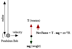
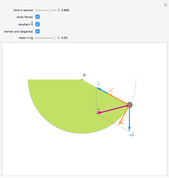
We treat the pendulum bob as a point particle. Drawing the free body diagram for the pendulum bob lets us write an expression for the net force acting on it. Define these variables:
Dynamics of the Elastic Pendulum
Find the equation of motion of this pendulum by taking the time rate of change of the angular momentum computed with respect to the pivot. ... Be sure to include a free body diagram. Pendulum with Torsional Spring - Solution: The free body diagram depicting the torques on the body is shown below. Note the directions of the unit

File:Conical pendulum.svg - Wikimedia Commons
Begin by drawing the free body diagram for the upper mass and writing an expression for the net force acting on it. Define these variables: T = tension in the rod; m = mass of pendulum; g = gravitational constant; The forces on the upper pendulum mass are the tension in the upper rod T 1, the tension in the lower rod T 2, and gravity −m 1 g ...
Conical Pendulum: Its time period, tension in string ...
2.1: By drawing a free body diagram for a simple pendulum and breaking the forces into components, show that the restoring force on a pendulum obeys equation 3 if we ignore friction and air resistance. (Hint: the net restoring force for a pendulum is the component of the sum of the forces that is perpendicular to the pendulum's string.) 2.2 ...
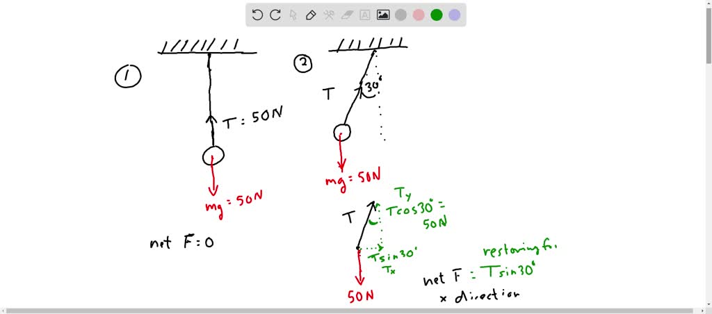
draw a free body diagram of a pendulum bob that has a 30 degree angle to the vertical a if the bob weighs 50 n label the values of all other forces and their components b what is the value of the rest
Next we draw the free body diagram for the pendulum. So we can write the net force as: F= Tcos θj− Tsin θi− mgj Using Newton's law F= maand the pendulum acceleration we found earlier, we have Tcos θj− Tsin θi− mgj= mR(θ''cos θi− θ'2sin θi+ θ''sin θj+ θ'2cos θj) Write the vector components of the above equation as separate equations.

A Beginner's Guide to Simulating Dynamical Systems with ...
-Rigid Body Kinematics x y z = cosθ sinθ 0 −sinθ cosθ 0 0 0 1 X Y Z i j k = cosθ sinθ 0 −sinθ cosθ 0 0 0 1 I J K . Derivation of Equations of Motion -Rigid Body Kinematics Free Body Diagram After substitutions and evaluation: Derivation of Equations of Motion-Lagrange Equations ... Spring Pendulum Dynamic System Investigation ...
Free Body Diagram of the Pendulum under Hydrodynamics Forces ...
Draw a free body diagram of a pendulum while in motion. (1 point) Measure the length of the pendulum in meters to 1 mm of precision L= 0.905 _(m) Data and ...
Energy Balance in a Revolving Virtual Pendulum System
Introduction: The Nature of Science and Physics · Two-Dimensional Kinematics

Free Body Diagram of Sliding Joint with Spring - CR4 ...
Draw free-body diagrams that conform to the assumed displacement positions and their resultant reaction forces (i.e., tension or compression). c. Apply to the free body diagrams to obtain the governing equations of motion. The matrix statement of Eqs.(3.123) is The mass matrix is diagonal, and the stiffness matrix is symmetric.
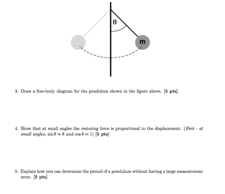
Solved Draw a free-body diagram for the pendulum shown in ...
To begin, we first draw the free-body diagram where the forces acting on the pendulum are its weight and the reaction at the rotational joint. We also include a moment due to the friction in the joint (and the rotary potentiometer).

Free Body Diagram of the Pendulum under Hydrodynamics Forces ...
A pendulum is a body suspended from a fixed support so that it swings freely back and forth under the influence of gravity. When a pendulum is displaced sideways from its resting, equilibrium position, it is subject to a restoring force due to gravity that will accelerate it back toward the ...

Free Body Diagram of Simple Inverted Pendulum - CR4 ...
body diagram Lecture 27. THE COMPOUND PENDULUM The term "compound" is used to distinguish the present rigid-body pendulum from the "simple" pendulum of Section 3.4b, which consisted of a particle at the end of a massless string. Derive the general differential equation of motion for the pendulum of figure 5.16a and determine its ...

CTM Example: Inverted Pendulum Modeling
March 24, 2019 - Index of /faculty

Finding equations of motion for pendulum on moving cart
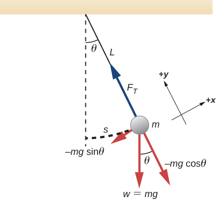
The second is tension in the string which changes in both size and direction as the pendulum swings. When it swings through the bottom of its arc, the pendulum has maximum speed and requires the maximum force to hold it in its circular path. The forces at the bottom are shown here in a free-body diagram.

Modeling a Pendulum's Swing Is Way Harder Than You Think | WIRED
About Press Copyright Contact us Creators Advertise Developers Terms Privacy Policy & Safety How YouTube works Test new features Press Copyright Contact us Creators ...

Modelling an inverted pendulum – deriving a mathematical ...
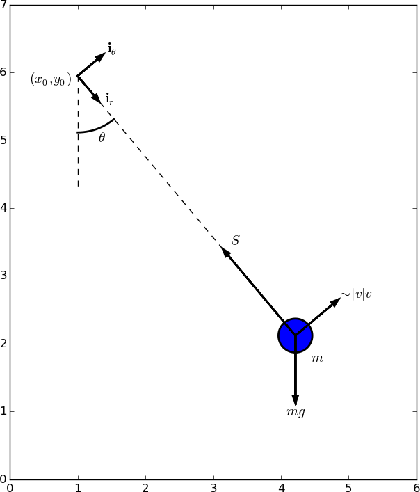
We begin by drawing and investigating a free body diagram, seen below. Note that we use polar coordinates instead of cartesian coordinates to simplify the problem greatly. Free Body Diagram of simple pendulum To derive the equations of motion, we start by setting up Newton's second law in the radial and anagular directions.
Using Pysketcher to Create Principal Sketches of Physics Problems
The force diagram on the pendulum is shown in Figure 24.4. In particular, there is an unknown pivot force and the gravitational force acts at the center of mass of the rod. Figure 24.4 Free-body force diagram on rod The torque about the pivot point P is given by P τ=r P,cm ×mg. (24.3.2)
Trig and forces: the pendulum (article) | Khan Academy
If you're seeing this message, it means we're having trouble loading external resources on our website · If you're behind a web filter, please make sure that the domains *.kastatic.org and *.kasandbox.org are unblocked
15.4 Pendulums | University Physics Volume 1
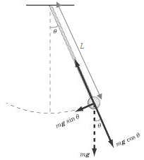
Let us consider the pendulum to be in simple harmonic motion, in this case, the restoring force, −mgsinθ − m g sin θ acting on the bob of the pendulum is ...
Solved] Create free Body Diagram (FBD) for the pendulum as it ...
Download scientific diagram | Free Body Diagram of the Pendulum under Hydrodynamics Forces from publication: Estimation of the Hydrodynamics Coefficients of an ROV using Free Decay Pendulum Motion. | A good dynamics model is essential and critical for the successful design of navigation and ...
Frontiers | Stabilization of a Cart Inverted Pendulum ...
September 19, 2016 - A simple pendulum is defined to have a point mass, also known as the pendulum bob, which is suspended from a string of length L with negligible mass (Fi...

Ballistic Pendulum Forces Immediately After Collision ...
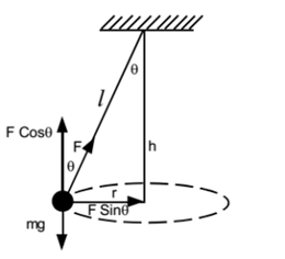
free body diagram in Fig. 6 below. Free Body Diagram Fig. 6 The free body diagram of the pendulum bob shows the gravitational force mg, the tension force T and the centripetal acceleration ac. The components of the gravitational force are also shown. Applying Newton's second law along the direction of tension force on gets T mg θ mgCos(θ)
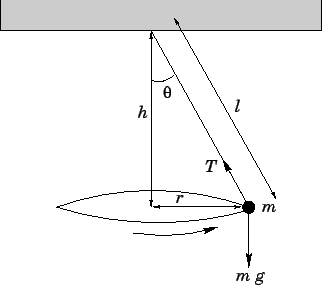
The conical pendulum
Energy of the Pendulum The pendulum only has gravitational potential energy, as gravity is the only force that does any work. Let us define the potential energy as being zero when the pendulum is at the bottom of the swing, θ = 0 . When the pendulum is elsewhere, its vertical displacement from the θ = 0 point is h = L - L cos(θ) (see diagram)
How to find the amplitude of a pendulum - Quora
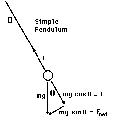
Free body diagram for a simple pendulum 2 . TEOSO er T ma Isine Accordingly ma = isnt F= ma = - masino 9 - - g sing So F = - masino F = - mgsint 2. 2. For Small Sin 0 4 Kicknow that F = - KX K = mg 2. 3 For Small Angle. W - X 9 L T = 27 = 2 17 W Q : The period varies as a function & length a ) it is directly proportional to the length.

Pendulum Free Body Diagram Lovely Pplato Flap - 2160x1934 PNG ...
Download scientific diagram | Conical pendulum and corresponding free body diagram. from publication: The Bravais pendulum: The distinct charm of an almost forgotten experiment | In the year 1851 in Paris, the apparent change of the plane of oscillation of a linear pendulum was observed by ...

Draw a free body diagram of a pendulum while in motion ...
COVID-19 vax update: You must upload proof before registering for on-campus classes this winter. Vaccination required for coming to campus. See all details here · lunaeduardo@deanza.edu

Inverted pendulum Equations of motion Force Free body diagram ...
- Pendulum angle label - Draw free body diagram 1. Let's start by the ground We will start by drawing the floor. We draw the components in a brown tone (brown!80!red) and add the dots using patterns TikZ library, which includes crosshatch dots option. Hence, the ground can be drawn in two steps:

Simple Pendulum
Double Pendulum • The disk shown in the figure rolls without slipping on a horizontal plane. Attached to the disk through a frictionless hinge is a massless pendulum of length L that carries another disk. The disk at the bottom of the pendulum cannot rotation relative to the pendulum arm. • Draw free-body diagrams and
Boxcar on an incline with pendulum
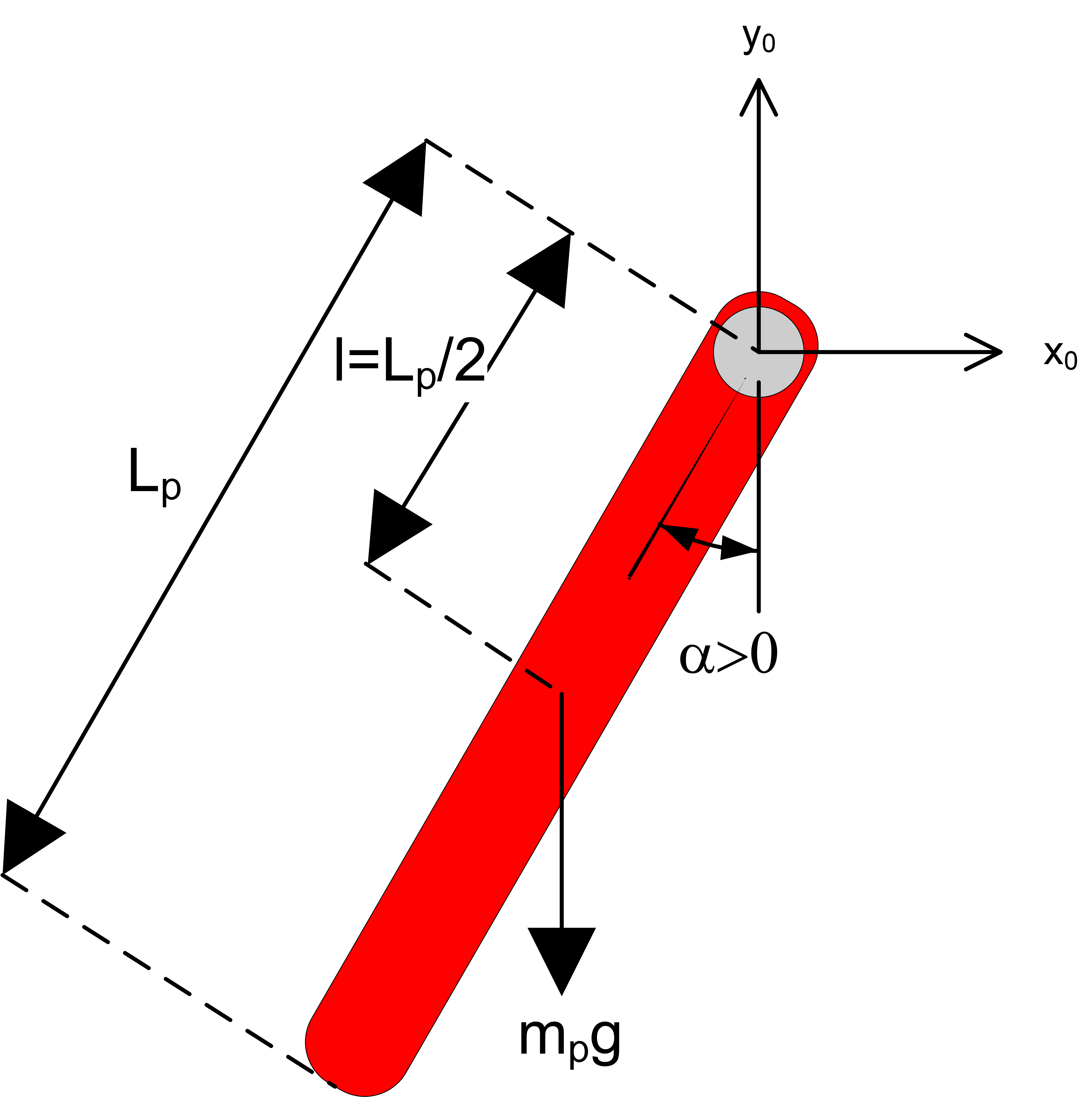
The force of the gravity can be decomposed into two components; one is parallel to the pendulum or the tension, and one perpendicular [3], as shown in Fig. 1.
I want to show you the pendulum I made for physics class
Dr. Massa and the great Orbax discuss the conical pendulum, drawing free body diagrams and centripetal acceleration.

PhysicsLAB: Derivation: Period of a Simple Pendulum
moving projectile. After the capture, the pendulum swings to a maximum opening angle of µ. Using conservation of momentum and energy, the initial velocity v of the projectile can be determine based on the opening angle µ. The center of mass of the pendulum is labeled "cm". Figure 3.2: The free-body diagram for the ballistic pendulum.
Control Tutorials for MATLAB and Simulink - Inverted Pendulum ...
A mass hanging from a string or attached to a rigid rod, i.e. a pendulum, is another example of a system which exhibits periodic motion. (In such a case, the mass is known as a bob.) The equilibrium position is when the string or rod hangs vertically. If the pendulum is not in this position, ...
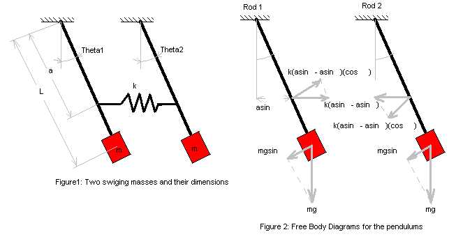
Derivations for Equations of Motion in a Two Pendulum System
Single and Double plane pendulum Gabriela Gonz´alez 1 Introduction We will write down equations of motion for a single and a double plane pendulum, following Newton's equations, and using Lagrange's equations. Figure 1: A simple plane pendulum (left) and a double pendulum (right). Also shown are free body diagrams for the forces on each mass.

Using the “Clicker†If you have a clicker now, and did not do ...
Check here to show the free-body diagram Purple is the true motion; orange is the comparison motion. This is a simulation of a simple pendulum (a ball attached to a massless rod). If the damping is set to zero, the pendulum moves without resistance. The larger the damping, the larger the resistive torque.
Pendulum
Centripetal Force - Pendulum Form

PhysicsLAB: Conical Pendulums
Forces on a Pendulum - Wolfram Demonstrations Project
Free body diagram of QUBE-Servo Pendulum - Quanser
0 Response to "40 free body diagram of a pendulum"
Post a Comment