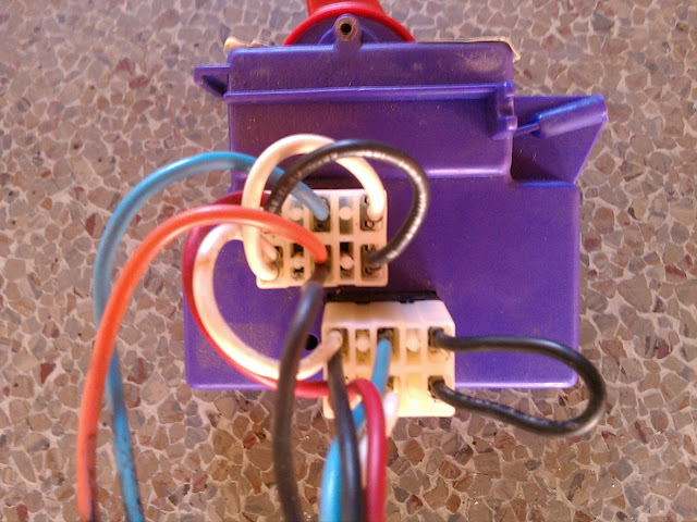
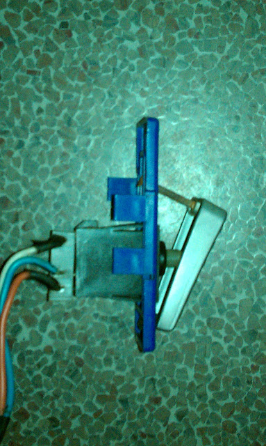
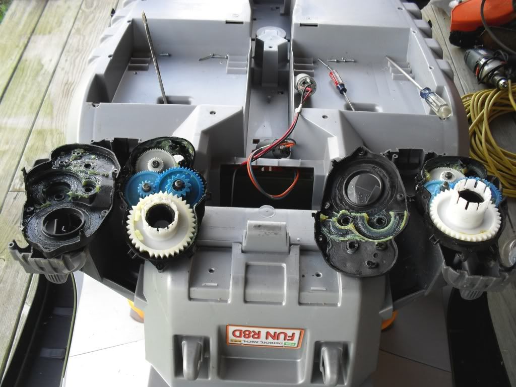
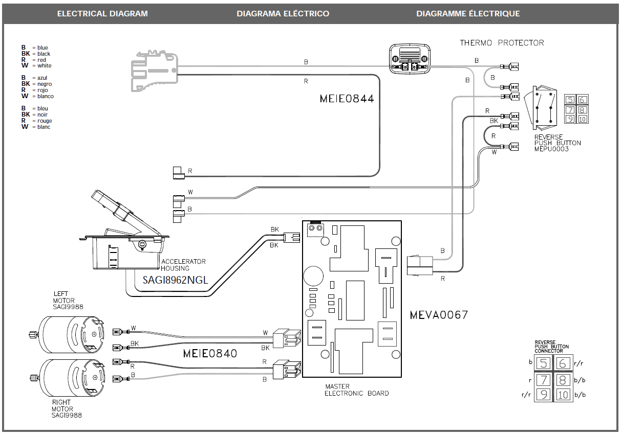
37 power wheels switch diagram
Plus, our PSX1 Power Stabilizers are compatible with most RVs and trailers on today’s market. Black Switch Configuration Details: SKU 298707 . Legs extend up to 30” Waterproof switch Includes: Switch and harness and reset breaker . Mounting hardware provided. 79” long x 6. 2” wide x 19” tall, 58 pounds Back to my inverter is instantaneous. The wiring diagram shown is not 100% accurate. It shows separate wiring/hookup for a charger that is only active when utility/generator power is on, there is not. Not a show stopper for my application, a typical Solar Power system with inverter and switch to utility/generator power when present.
Find the Whiteman Walk-Behind Concrete Power Trowel model you own in the diagram listings shown below. Each link will take you directly to that model Whiteman Walk-Behind Concrete Power Trowel parts list and part view diagram. Be sure to have your correct Power Trowel model number and serial ready when locating your parts.

Power wheels switch diagram
Diagram. Description. In this scenario, the first switch is "on" and the second switch is "off." Power flows from the first switch to the second switch over traveler 1 but doesn't make it to the light fixture. In this scenario, both switches are "on." Power flows from the first switch to the second switch over traveler 1 and the light turns on. 16 12v Ride On Car Wiring Diagram Car Diagram Wiringg Net In 2020 Power Wheels Diy Electric Car Electric Car . 2 Way Rocker Switch Wiring Diagram Motorcycle Wiring Light Switch Wiring 12v Led Lights . 12 Volt Wiring Diagram Electrical Diagram Caravan Electrics Vintage Camper Remodel . In a typical household electrical circuit, the black circuit wires (and sometimes red) are the "hot" wires that carry power from the source to the switch or receptacle. The white wires are "neutral" and carry the electricity back to the home's service panel (breaker box) after it flows through all of the devices or fixtures in the circuit.
Power wheels switch diagram. Some components (bus bars, cables, switch, fuses,etc.) in this diagram are cheaper (and smaller) because they're rated for lower current. Maybe you don't need shore power or inverter at all? Download This Wiring Diagram & Tutorial (pdf) Keystone Rv Wiring Diagram - keystone cougar rv wiring diagram, keystone rv cable tv wiring diagram, keystone rv tv wiring diagram, Every electric structure consists of various distinct parts. Each part should be set and linked to different parts in particular manner. Otherwise, the arrangement will not function as it should be. Power Take-Off Unit (Pto): It is a part of tractor transmission system. It consists of a shaft, a shield and a cover. The shaft is externally splined to transmit torsional power to another machine. A rigid guard fitted on a tractor covers the power take-off shaft as a safety device. This guard is called power take-off shield. Kohler K321 Wiring Diagram. Kohler k321 6041 basic 14 hp 10 4 kw specs 6006 60443 parts diagram for ignition tp 691 b rev 18 2006 14hp charging system yesterday s tractors wiring diagrams to help you understand how it is done electrical redsquare wheel horse forum what draining the battery smokstak antique engine community horwool woes k301 ...
Basic points ignition wiring diagram wiring diagram is a simplified satisfactory pictorial representation of an electrical circuit it shows the components of the circuit as simplified shapes and the power and signal connections between the devices. If used for 6 volt make all the wires heavier by 2 gauges. How to Wire a 12V Fuse Block to the Battery Bank. In all of the EXPLORIST.life solar wiring diagrams, I have integrated the WFCO WF-8950 into every one to deliver power to all of the 12V accessory runs.The following diagram highlights the path from which the 12V power distribution panel draws power from the battery bank. 12V power is drawn from the 12V Battery bank and gets distributed through ... How to wire a relay switch diagram. In this post, i am sharing a simple 5 pin relay wiring diagram. A wiring diagram is an common pictorial depiction of a complicated electric circuit. The two schematic wiring diagrams below show how to wire an electrically latching relay circuit. Nov 23, 2021 · This is a small grinder operated with electric power. It can be easily carried anywhere. Grinding can be done by holding it in hand. It is used for cleaning heavy welding jobs. On one end of the motor shaft, a grinding wheel is fitted and on the other end, a handle or switch for operating the machine is fixed according to our convenience.
A railroad car's wheels are guided along the tracks by coning of the wheels. Only in extreme cases does it rely on the flanges located on the insides of the wheels. When the wheels reach the switch, the wheels are guided along the route determined by which of the two points is connected to the track facing the switch. Artwork: A typical reed switch flow meter works something like this. There's a pipe through which liquid flows (1) with a paddle wheel mounted inside it (2). As the liquid flows, the paddle spins and makes a magnet rotate (3). The rotating magnet makes a reed switch open (4). The diagram below shows which wheels are powered in each position. Operate in Turf Mode only as needed to protect smooth, level surfaces from tire damage. Do not operate in Turf Mode when climbing or descending hills, when sidehilling or when operating on uneven, loose or slippery terrain such as gravel, ice, snow, obstacles and water crossings. The diagram above shows the typical bare-bones OEM RV/Camper with 50A shore power service. Shore power flows into the breaker box, powering the breaker box protected by a 50A breaker where 240v power is divided up into 2 legs of 120V power to power both sides of a breaker box. One circuit is generally the Converter.
7.3L Wiring Schematic Printable, very handy. Handy Wiring Diagram that shows a Paper Trail of how the Electrical System Works for the 7.3L Powerstroke Engines, all Trucks, Excursions, Vans. It was a Copy I had to PhotoShop to make it Readable & Printable. it's very detailed and shows how every wire for each component routes to the PCM.
Holiday Rambler Wiring Diagram - 1972 holiday rambler wiring diagram, 1984 holiday rambler wiring diagram, 2000 holiday rambler wiring diagram, Every electrical arrangement consists of various distinct pieces. Each component should be placed and connected with other parts in particular way. If not, the arrangement will not work as it ought to be.
The IEC 60320 C13 14. Ac power cord wiring diagram. The Different Types of AC Power Connectors in North America. 2-wire grounded DC Power System. 3-wire grounded DC Power System. In this mode loads connected to the AC output. Note the reversal of the Active and Neutral wires depending on whether you are wiring a socket or a plug.
Each wiring diagram provides: a detailed wiring diagram for the given size - both series and parallel, what you can reasonably expect to power with a system of that size, tips for future scaleability, a complete shopping list of parts needed for a DIY installation and; where available, pre-configured solar panel kits.
Basic Safe Electric Fuel Pump Wiring Diagram This is the basic wiring diagram for SAFE electric fuel pump wiring. The diagram is color coded per circuit and only a few things may need to be said. Fuel pump wiring for the RED circuit is generally going to carry a much higher current than the relay. So use a larger gauge wire for lower voltage drop.

Image from page 580 of "Railway and locomotive engineering : a practical journal of railway motive power and rolling stock" (1901)
F48 30 c.b. Master window control switch. Overhead console switch. 2011 Ford F150 Fuse Diagram for Passenger Compartment Fuse Box. 1 30A Driver side front window 2 15A SYNC 3 30A Passenger side front window 4 10A Interior lamps 5 20A Memory module 6 5A Not used (spare) 7 7.5A Power mirror switch, Memory seat module 8 10A Not used (spare)
{{ vm.RepairShellService.searchResultsCount }}
The switch disconnects the battery's electrical power or isolates from the house portion of your RV. This prevents parasitic loads such as the stereo, clock, and other appliance circuitry that lead to discharge. Leaving alone without regular charging will damage even the best RV battery.
The common circuit diagram of the push-pull SPDT SSR relay as shown below (as shown in Figure 7). The push-pull type SPDT SSR switch consists of two LEDs (D1, D2), and two Photo-TRIACs (TRIAC1, TRIAC2). D1 and TRIAC1 form the CIRCUIT1, and D2 and TRIAC2 form the CIRCUIT2.
In a typical household electrical circuit, the black circuit wires (and sometimes red) are the "hot" wires that carry power from the source to the switch or receptacle. The white wires are "neutral" and carry the electricity back to the home's service panel (breaker box) after it flows through all of the devices or fixtures in the circuit.
16 12v Ride On Car Wiring Diagram Car Diagram Wiringg Net In 2020 Power Wheels Diy Electric Car Electric Car . 2 Way Rocker Switch Wiring Diagram Motorcycle Wiring Light Switch Wiring 12v Led Lights . 12 Volt Wiring Diagram Electrical Diagram Caravan Electrics Vintage Camper Remodel .
Diagram. Description. In this scenario, the first switch is "on" and the second switch is "off." Power flows from the first switch to the second switch over traveler 1 but doesn't make it to the light fixture. In this scenario, both switches are "on." Power flows from the first switch to the second switch over traveler 1 and the light turns on.





![[XK_2573] Trends Of Power Wheels 12 Volt Wiring Diagram ...](https://static-resources.imageservice.cloud/11234446/power-wheels-dune-racer-extreme-12-v-battery-powered-ride-on-green.jpeg)




![[XV_8803] Trends Of Power Wheels 12 Volt Wiring Diagram ...](https://static-resources.imageservice.cloud/11234454/wiring-diagram-1999-jeep-back-door-shelectrikcom.jpg)


![[SM_6154] Modified Power Wheels Faq Parallel Series Wiring ...](https://static-cdn.imageservice.cloud/1641618/amazoncom-mltoys-stage-ii-speed-motors-gearboxes-power-wheels.jpg)

0 Response to "37 power wheels switch diagram"
Post a Comment