41 toyota circuit open relay diagram
1. NORMALLY OPEN. RELAY, DOUBLE THROW. A relay which passes current through one set of contacts or the other. RESISTOR. An electrical component with a fixed resistance, placed in a circuit to reduce voltage to a specific value. RESISTOR, TAPPED. A resistor which supplies two or more different non adjustable resistance values.
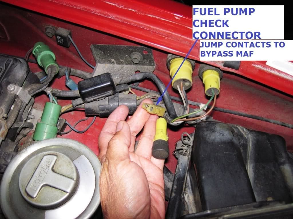
Sep 7, 2008 — A circuit opening relay can be used to run a electronic fuel pump in an EFI car. The circuit opening relay provides power to the fuel pump ...
Dual Contact (Single Relay), Ignition Switch Controlled This EFI Main Relay configuration is used on the Conventional eFi system. It uses separate power contacts to supply current to the fuel injector/ignition circuits and the ECU/circuit opening relay circuit. This limits current flow that the ECU power contact must handle.
Toyota circuit open relay diagram
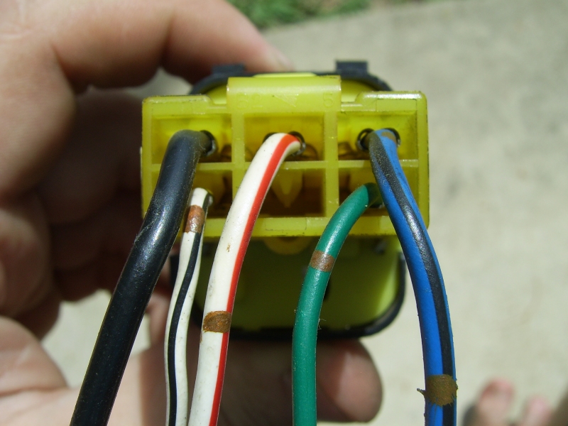
Feb 6, 2019 — PLEASE DOUBLE CHECK WIRE COLORS AND SCHEMATIC AGAINST YOUR OWN FSM BECAUSE SOME TRUCK WIRING MAY TRANSITION DURING A YEAR.
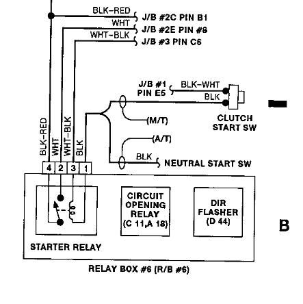
As long as the neutral safety switch is in the park position (or the clutch safety switch is closed), the relay closes, allowing voltage to flow to the starter solenoid. The solenoid then engages the starter to crank the engine. An example of a modern computer-controlled starter solenoid wiring diagram.
Circuit Opening Relay Wiring; Circuit Opening Relay Pinouts ... the engine ECU has a dedicated output pin (Usually labelled FC in Toyotas) that is connected ...Circuit Opening Relay Function · Circuit Opening Relay Operation
Toyota circuit open relay diagram.
2. About Bypass Toyota Hilux Immobilizer Read Online Fuse Box Engine Main Toyotabox diagram – engine compartment relay box. The entire circuit is thus in a ...
Swagatam, regarding the uln2003 circuit, I am unable to fulfil my requirements which are as follows:-1.pin 7 of ic uln2003 will go to the sensor in the sump which should switch on the relay with output from pin 10. 2.pin 16 should switch off the same relay and the pump for the OH tank.
Diagnostic trouble code (DTC) code P0201 stands for "Cylinder 1 Injector Circuit/Open.". It indicates a potential problem with the #1 Fuel Injector Circuit, like a broken wire, loose terminal, burned out injector coil, or some other circuit interruption issue. When the injector on an MPI unit is grounded, the injector pintle raises off its ...
All Toyota Camry XV50 info & diagrams provided on this site are provided for general information purpose only. Actual Toyota Camry XV50 (2011-2017) diagrams & schemes (fuse box diagrams & layouts, location diagrams, wiring diagrams etc.) may vary depend on the model version.
As shown in the following circuit diagram, the relay driver may consist a NPN transistor or a PNP transistor. Circuit Operation. If it's a PNP transistor, the base is coupled at the collector of the photo transistor, alternatively, if a NPN transistor is used in the relay driver, the trigger is received from the emitter of the photo transistor ...
System Circuit Diagrams. The entire EWD is built around the System Circuit Diagram. Every number, letter, shape, and shading on the diagram tells you information that can help you to locate or identify components on the car faster. RADIATOR FAN AND CONDENSER FAN (5S-FE) RADIATOR FAN AND CONDENSER FAN (5S-FE) Understanding the System Circuit Diagram
Under the instrument panel diagram. All Toyota Camry XV40 info & diagrams provided on this site are provided for general information purpose only. Actual Toyota Camry XV40 (2006-2011) diagrams & schemes (fuse box diagrams & layouts, location diagrams, wiring diagrams etc.) may vary depend on the model version.
The fuses are designed to blow before the entire wiring harness is damaged. All Toyota Tundra II info & diagrams provided on this site are provided for general information purpose only. Actual Toyota Tundra II (2007-2018) diagrams & schemes (fuse box diagrams & layouts, location diagrams, wiring diagrams etc.) may vary depend on the model version.
12V type 0.2 ft 24V type 0.9 O. 6. Check glow plug relay. (1) Pull the stop button all the way out, or disconnect the connector of EDIC motor wires to prevent accidental starting of the engine. (2) When the starter switch is turned to the "START" position, a voltage should register at "S" terminal. 1.
Re: 1988 Toyota Pickup 22re EFI need help troubleshooting a FP B+ jumper ''NO FP ON'. when its cold, turn key to almost start, should hear click near glovebox, that's the open circuit relay, once it dies,after its warm, try listening for the click, if no click, bad OCR. Even the most primitive society, has an intimate respect for the insane.
TOYOTA CAMRY ELECTRICAL WIRING DIAGRAM CONTENTS INTRODUCTION HOW TO USE THIS MANUAL ABBREVIATIONS ... RELAY LOCATIONS ELECTRICAL WIRING ROUTING SYSTEM CIRCUITS GROUND POINT POWER SOURCE (Current Flow Chart) ... Provides circuit diagrams showing the circuit connections. Download here. Read More ->> Newer Posts Beranda.
A latching relay is used to control the large flow of current with a smaller current. The coil of the latching relay consumes power only while the relay is switched ON. And its contact remains in position after the switch has been released. See the latching relay circuit diagram below for more details on how this works.
Location of circuit opening relay - 94 4runner - yotatech forums
This circuit is more effective and easier to install than the conventional magnetic reed relay type intrusion alarm. Here the circuit utilizes a IC 555 timers as a one shot timer for sounding the alarm. The air gap slot of the optoisolator is blocked with a lever kind of attachment, which is also integrated to the window or the door.

Fuel circuit opening relay location? - yotatech forums
Some relays show a circuit diagram on top of the case to identify these terminals. Check for continuity between the two power terminals using an ohmmeter. There should be no continuity. If there is continuity, replace the relay. Connect a jumper wire between, the battery positive terminal and one of the control circuit terminals on the relay.
Wilbo666 / circuit opening relay
Download original OEM wiring diagrams manual for the 2000-2005 Toyota RAV4 in a simple PDF file format. ... When the circuit operation is understood, begin troubleshooting of the problem circuit to isolate the cause. Use Relay Location and Electrical Wiring Routing sections to find each part, junction block and wiring harness connectors, wiring ...
Open circuit relay | toyota nation forum
Compustar CM900S, 2001 Toyota Sequoia - Hello all and Happy Thanksgiving to everyone. I need some help from the pros. Just got done wiring a compustar cm 900s remote start into my 2001 Toyota Sequoia. I added an immobilizer bypass for the chipped key and the truck starts remotely fine. The problem i

For 1993-1998 toyota t100 circuit opening relay smp 52158qc ...
File Size: 29.4 MB. Delivery Method: Instant Free Download. This EWD (Electrical Wiring Diagrams) service manual is used in the inspection and repair of the electrical circuits of 2003-2009 Toyota Avensis. It provides information on the electrical circuits installed on vehicles by dividing them into a circuit for each system.

I have a 1990 toyota truck 3vze i am not getting 12v at the ...
Electrical Diagram Software You can use the built-in electrical symbols to make well-crafted electrical diagrams in minutes. So it has become quite easy to create schematics, wiring diagrams, circuit diagrams and other electraical diagrams.Select from switches, relays, transmission paths, semiconductors, power sources, batteries, integrated circuit components, etc.

Testing toyota circuit opening relay #6 | repair guide, relay ...
Referring to the shown, simple gate open, close controller circuit below, we can witness a rather straightforward configuration, essentially comprising of a transistor latch stage, a DPDT relay stage and a few push to ON/OFF switches. The push switches S3/S4 play an important role in the circuit and ensure that the motor never gets overloaded ...

Inspection of circuit opening relay - toyota mr2 mk2 1991 ...
1) Push-Pull Type SPDT Solid State Relay. The common circuit diagram of the push-pull SPDT SSR relay as shown below (as shown in Figure 7). The push-pull type SPDT SSR switch consists of two LEDs (D1, D2), and two Photo-TRIACs (TRIAC1, TRIAC2). D1 and TRIAC1 form the CIRCUIT1, and D2 and TRIAC2 form the CIRCUIT2.

Wont start can bypass fuel pump and it works work .fuse good ...
The relay does power the male pin in the socket as required. Thus no green wire going to the stop lamp. So I will procure a terminal from the same Tundra that donated the switch and run the lights under the cab, through the rubber plug in floor pan under seat and into the sill plate harness space on left side.
Open circuit relay | toyota nation forum
Schematic Diagram Circuit Diagram Is used in various industries, including but not limited to electrical engineering, buildings, constructions, chemistry, and etc. Is used only to illustrate how an electronic or electric circuit has to be prepared. Consists of industry-specific lines and symbols to illustrate the idea or concept.
Short efi relay circuit: i bought a 1993 camry 2.2l recently ...
(All circuit diagrams are shown with the switches in the OFF position.) When troubleshooting any problem, first understand the operation of the circuit where the problem was detected (see System Circuit section), the power source supplying power to that circuit (see Power Source section), and the ground points (see Ground Point section).

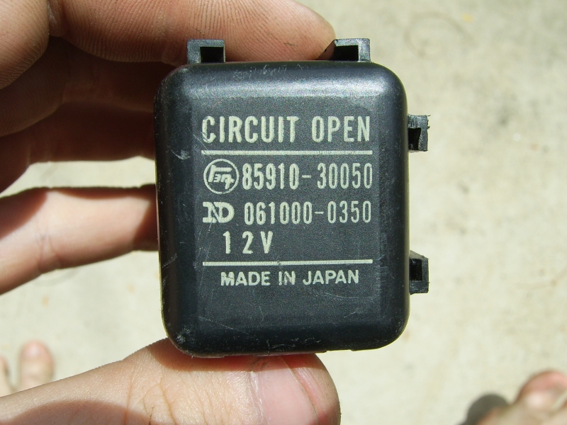
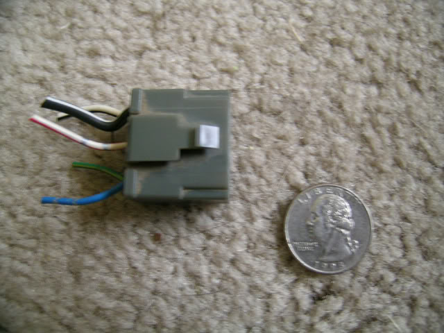
Fuel circuit opening relay 85910-30050 toyota previa camry 91-95 pickup 4runner | ebay
This is the complete circuit diagram for this home automation project. I have explained the circuit in the tutorial video. The circuit is very simple, I have used the GPIO pins D1, D2, D5 & D6 to control the 4 relays. And the GPIO pins SD3, D3, D7 & RX are connected with push buttons to control the 4 relays manually.. I have used the INPUT_PULLUP function in Arduino IDE instead of using the ...
1995 fzj80 circuit opening relay | ih8mud forum
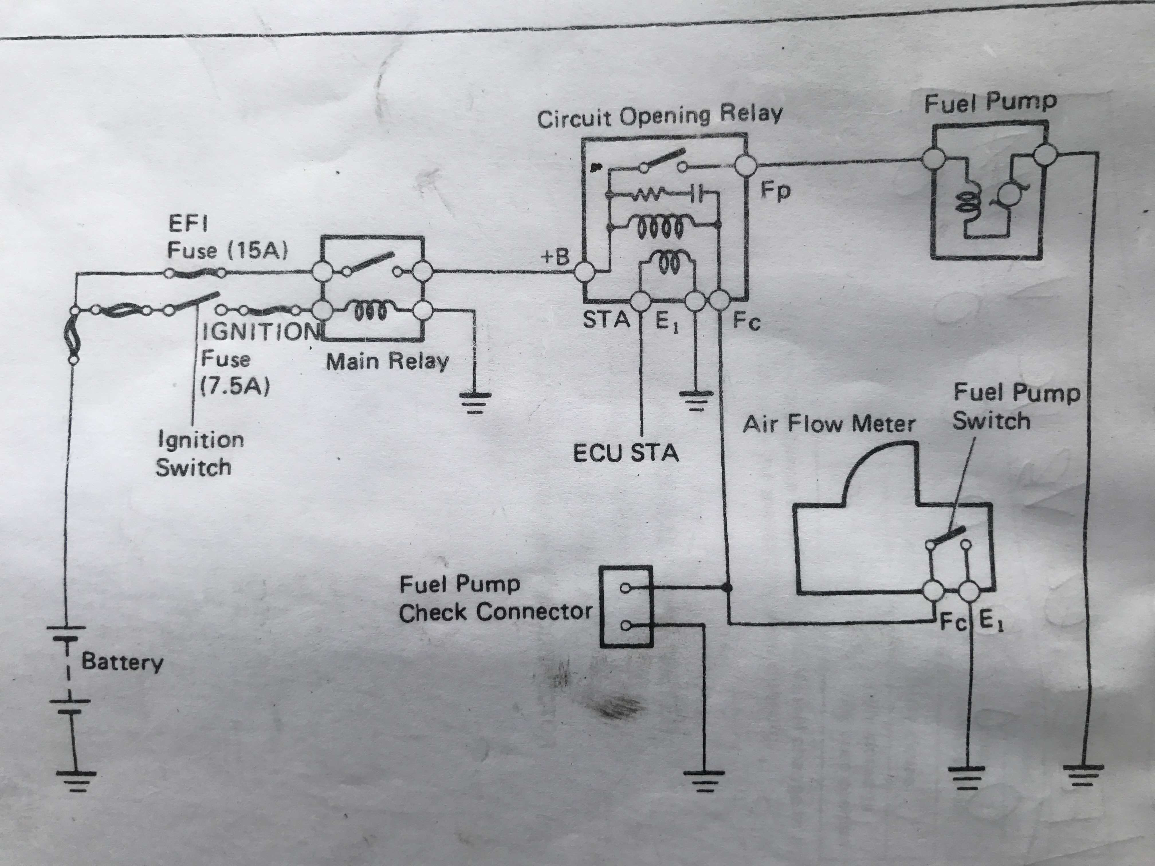
Circuit Opening Relay Circuits There are three types of fuel pump control circuits used on Toyota's EFI engines. One type of control, used exclusively with L type injection, utilizes the air flow meter Fc contact to complete the circuit opening relay run winding ground. This is a safety feature which prevents the fuel pump from operating when ...

Circuit-opening relays on toyotas | bluetwentyeight ra28 ...
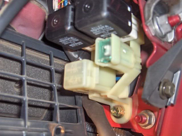
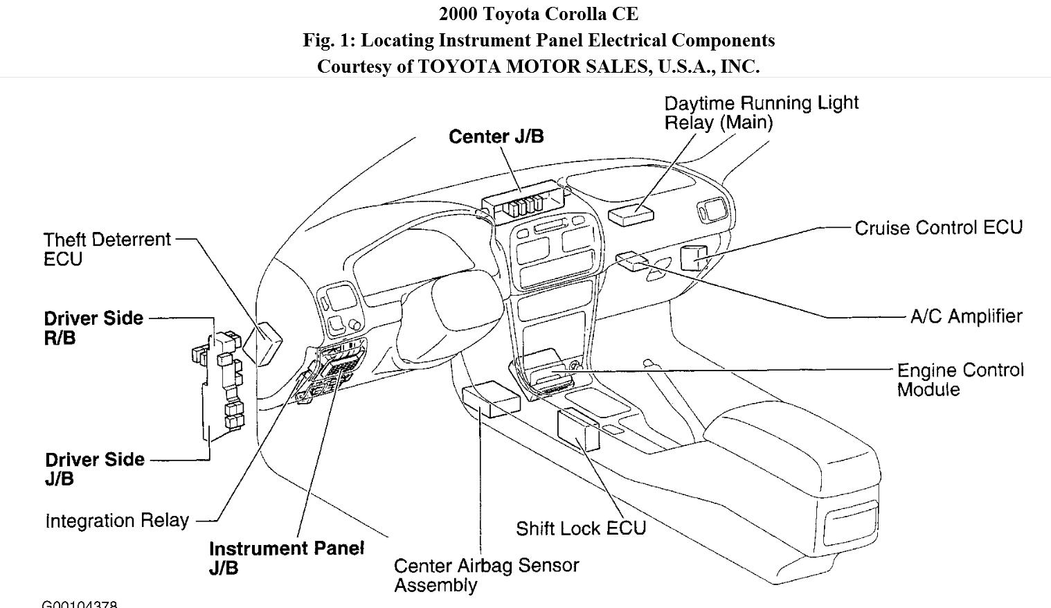
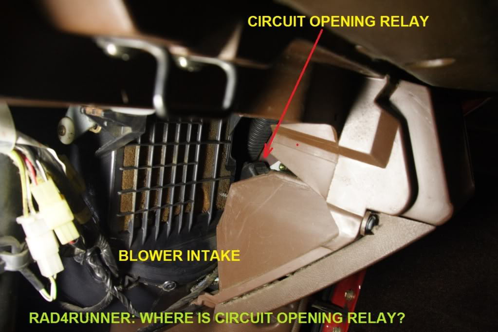
There are two relays that are involved, the circuit opening relay located behind the glove box and the EFI main relay located in the fuse box under the hood, the most common problem when there is no fuel pressure is the fuel pump, check all the fuses and substitute the two relays to see if it solves the problem.

Fuel pump electrical controls and circuit opening relay ...
Apr 24, 2017 — As I was wiring up my 1GGZE I came across this weird device called a Circuit-opening Relay (COR). I had no idea what it does, how to wire it ...
Circuit opening relay location??? | tacoma world
Sebagai contoh, dengan Relay yang memakai Elektro-magnet sekitar 5V dan 50 mA mampu menggerakan Armature Relay (yang fungsinya sebagai saklarnya) untuk menghantarkan listrik 220V 2A.Gambar Bentuk dan Simbol Relay. Dibawah ini merupakan image bentuk Relay dan Simbol Relay yang sering banyak orang temukan di Rangkaian Elektronika.
Where is the circuit opening relay? i have power through the ...

I believe the circuit opening relay for my 93 camry is bad ...
Circuit opening relay | ih8mud forum
Circuit opening relay wiring - rollaclub
Circuit opening relay wiring - rollaclub
![Sustituto De Circuit Open Relay De Toyota Pik Up 22re [PDF|TXT]](https://html.pdfcookie.com/02/2020/01/02/mly0e6xjep20/bg1.jpg)
Sustituto de circuit open relay de toyota pik up 22re [pdf|txt]

Fuel pump whines at on & doesn't shut off, circuit opening ...

Where is the circuit opening relay located on a 1994 toyota ...
How circuit opening relay works - toyota 4runner forum ...
Circuit opening relay | ih8mud forum
Circuit opening relay location??? | tacoma world
Fuel pump whines at on & doesn't shut off, circuit opening ...

Circuit opening relay - toyota mr2 mk1 1989 aw11 repair

Gsic - global service information center

Fuel pump electrical controls and circuit opening relay ...

22re no power to fuel pump? how to bypass circuit opening relay

Toyota circuit opening relay cheap fix

Fuel pump circuit opening relay 85910-35010 89-95 toyota ...

Circuit-opening relays on toyotas | bluetwentyeight ra28 ...
Location of circuit opening relay - 94 4runner - yotatech forums
How circuit opening relay works - 22r-eliable - yotatech forums

Circuit opening relay - toyota mr2 mk1 1989 aw11 repair
Where is the efi main relay located?? - toyota 4runner forum ...

Fuel pump electrical controls and circuit opening relay ...
0 Response to "41 toyota circuit open relay diagram"
Post a Comment