40 7127 alternator wiring diagram
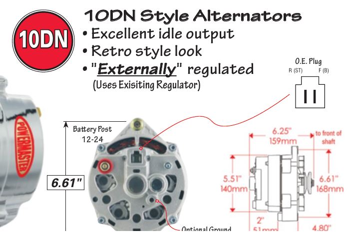
WIRING INSTRUCTIONS GM SI Alternator (One Wire or OE Hookup) Tech Dept. (630) 957-4019 Tech@powermasterperformance.com Replaces these OEM Alternators GM 10DN Externally Regulated GM 10SI Internally Optional Charge Indicator Light Function: Your Powermaster Alternator is designed to work as a 1 wire without any connections to the plug in. The Chevy Alternator Swap Toyotaoffroad Com. Wiring a delco gm alternator type cs130 series how to wire an ac 3 catalog do i 4 g questions hot mins marine style alternators remey 22si serpentine billavista com tech self build adjule controler 11 89 volts while running el camino two ignition chevy swap toyotaoffroad 12v dc part 2 ls conversion information 6bta5 9 m3 diagram weldingweb welding ...
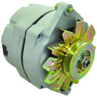
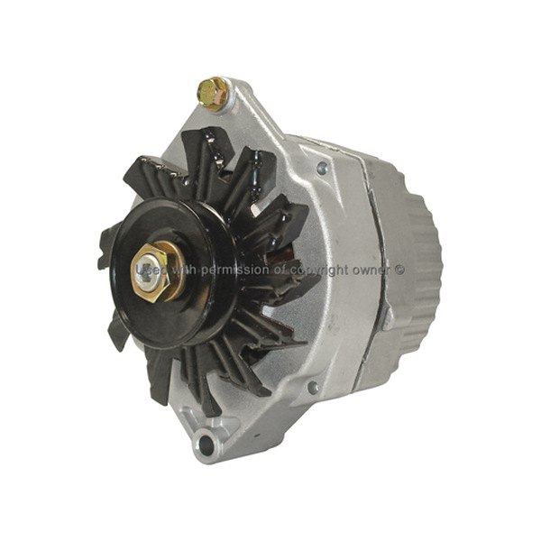
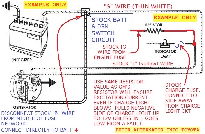
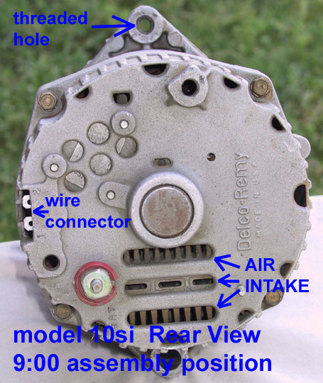
I reference the Delco alternator used in most GM late 70's cars and trucks with a 350 cu. in. V8 engine. (Type #GM 10 SI, Model 7127, Cost is roughly $35), but nearly all internally regulated alternator's have the same output wiring. I used a Datsun alternator for my Massey Ferguson because the diameter was the same as the original generator.

7127 alternator wiring diagram
Dei 555l Wiring Diagram; Kinter Ma-150 Wiring Diagram; 7127 Alternator Wiring Diagram; Aaon Rn Series Wiring Diagram; Cub Cadet Lt1042 Belt Diagram; Ka24de Distributor Wiring Diagram; Diagramming The Scriptures; Sterling Gas Heater Wiring Diagram Qvf 75; Wiring Diagram For Reliance 606 Water Heater; 1620 Ford Tractor Wiring Diagram | Tricia Joy ... Cs144 Wiring Diagram- wiring diagram is a simplified up to standard pictorial representation of an electrical circuit.It shows the components of the circuit as simplified shapes, and the capacity and signal links between the devices. A wiring diagram usually gives counsel just about the relative twist and covenant of devices and terminals on the devices, to put up to in building or servicing ... If you jump the no.2 wire to the batt wire on the back of the alternator, it will work, but you are setting up a chronic low charge condition. The number 2 terminal is used to sense system voltage, and if it is seeing 12.5 volt at the alternator it shuts it down, when the rest of the system may be seeing only 11.8.
7127 alternator wiring diagram. 7127-3n, 8134663, 8982775004, jr775004, 10495382, 1100110, 1100111 GMC Alternator. 7127-3N. NEW. $89.07. Buy. Bobcat Skid Steer Loader Alternator, Buick Car Alternator, Case Combine Alternator, Chevrolet Car Alternator, Chevrolet Medium and Heavy Duty Trucks Alternator, Chevrolet Truck Alternator, Chevrolet Van Alternator, GMC Medium/Heavy ... 9 - If installing an alternator with OEM wiring connections, reconnect alternator wires and battery ground cable. If installing a 1-wire alternator, see wiring instructions at upper right. 10 - Make sure battery is fully charged before starting engine. 11 - Reconnect the ground cable, start the engine and using a VOM meter, verify that the ... How to wire alternator diagram. To wire a warning light remove the terminal plug cover and connect the 1 Left terminal looking from the back of the alternator to the warning light wire. It shows the components of the circuit as simplified shapes and the power and signal associates together with the devices. Step 6 Figure 1 Snap in the DA plug ... Alt Wire Diagram Alternator Wiring And Out The Dash Warning Light - 12 Volt Alternator Wiring Diagram. Wiring Diagram arrives with several easy to stick to Wiring Diagram Directions. It's supposed to assist all the typical user in developing a suitable method. These guidelines will likely be easy to grasp and apply.
Jan 4, 2006 — The voltage regulator installed in a single wire alternator is a self exciting design(that's pretty exciting), but it has the two tabs where the ... * The 7127 / 321-39, 63 amp alternator is a very common inexpensive alternator that just about everyone keeps on the shelf and is a good choice for most Series Land Rovers. It has been the choice of hot rodders with carburatted engines for a couple decades because it is cheap, easy to come by and works well. It is very important to use the correct wire size to connect the alternator to the battery. A wire size too small can allow the wire to overheat, melt the insulation and cause a fire or worse. Depending upon the maximum output of the alternator, use the following chart as a minimum wire size guide. Wire size is based on 4' battery cables. You have only had the large BATT wire connected in the circuit and it has performed properly. Now you want to connect the DA plug wires. Stuart. Copy Link to Clipboard. Re: 7127 alternator question. #94171 Wed Jan 04 2006 04:13 PM. Joined: Jul 2005. Posts: 2,046. nor cal foothills.
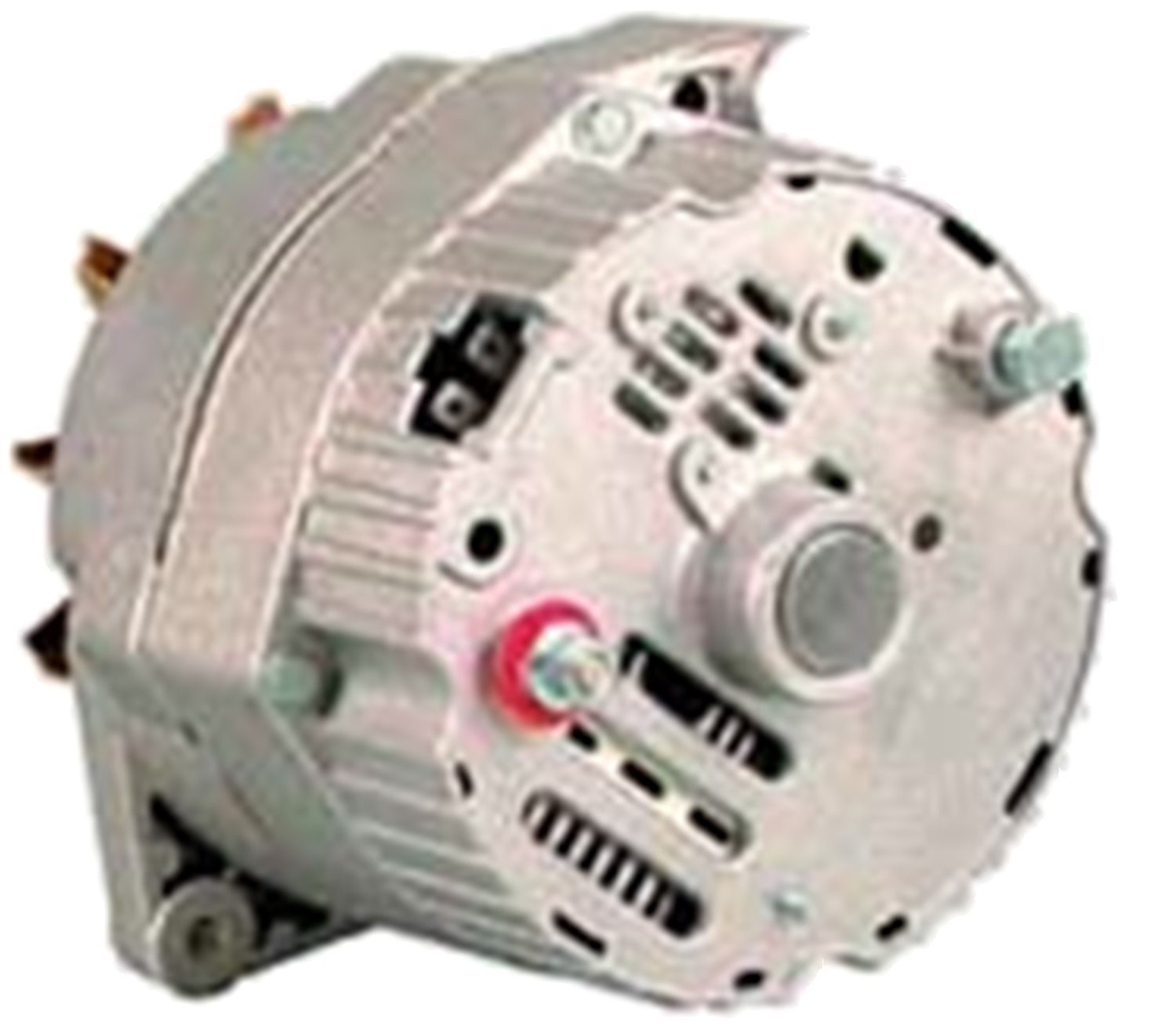
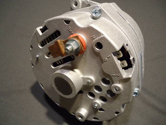
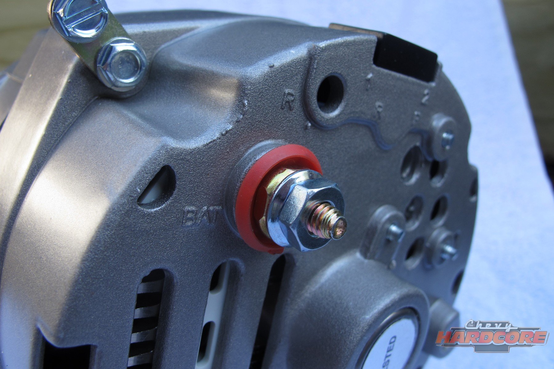
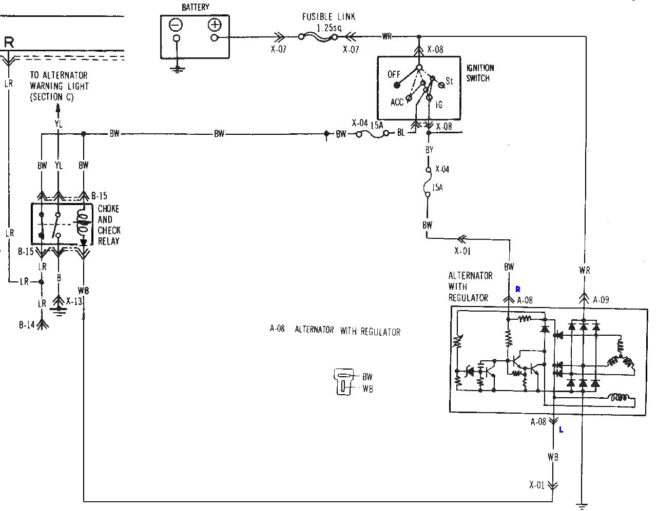
7127 Alternator Wiring Diagram. Remove the voltage regulator plug connector from the original alternator. 4. For Delco applications without tachometer, use wiring harness adapter P/N ( universal .. 63 ALN. 63 ALN. 63 ALN. try this schematron.org . Pretty much all 3 wire alternators come with a wiring diagram to explain where the #1 and #2 wires go. Understanding the Alternator • Four wires connect the alternator to the rest of the charging system. • B is the alternator output wire that supplies current to the battery. • IG is the ignition input that turns on the alternator/regulator assembly. • S is used by the regulator to monitor charging voltage at the battery. The 7127 uses negative ground, and is a 3 wire alternator. Below are some pics of my Farmall H. The 7127 is too large for the hood to latch, but the use of an idler pulley solves that problem. It allows the alternator to be mounted against the engine while using the idler to adjust belt tension. 7127-SEN (201021) Delco Type 10Si Series Alternator - 63 Amp/12 Volt, CW, 1-Groove Pulley, 1-Wire System Used On Farm & Industrial Applications Lester Nos 7127-SE
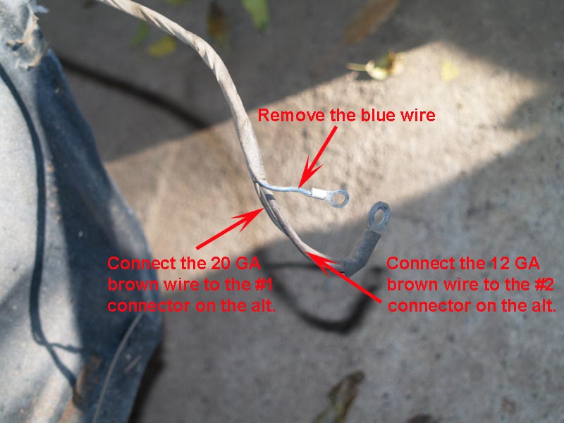
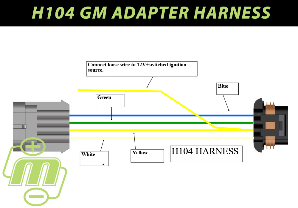
7127-3 63 AL9971N 7127-6 63 AL9971N 7127-9 63 AL9971N 7127-12 63 AL9971N 7133 55 AL9971N 7137-6 70 AL9971N 7178-12 61 AL9971N Lester (Cont'd) ... Take the blue wire from the original alternator and attach it to the D+ terminal of the new Bosch alternator. 6. Attach the original B+ cable to the B+ terminal of the new Truck Harness Plug
Installed on race car in 1 wire setup, have not had any issues with it draining the battery down. Car will sit for 1 to 3 weeks at a time and has never failed to start . Installed on car by running one wire from alternator, all the way back to positive battery post! PAUL M from LA | 4/2/2020. 0 of 0 found this answer helpful.
Some shimming or modification to the alternator mount may be required to assure proper alignment. 6. Connect the output cable (see cable sizing recommendations below) ground, field wire, stator (tach) wire if needed and other necessary wiring. Connect alternator to Balmar regulator wiring harness as indicated in wiring diagram included on Page 12.

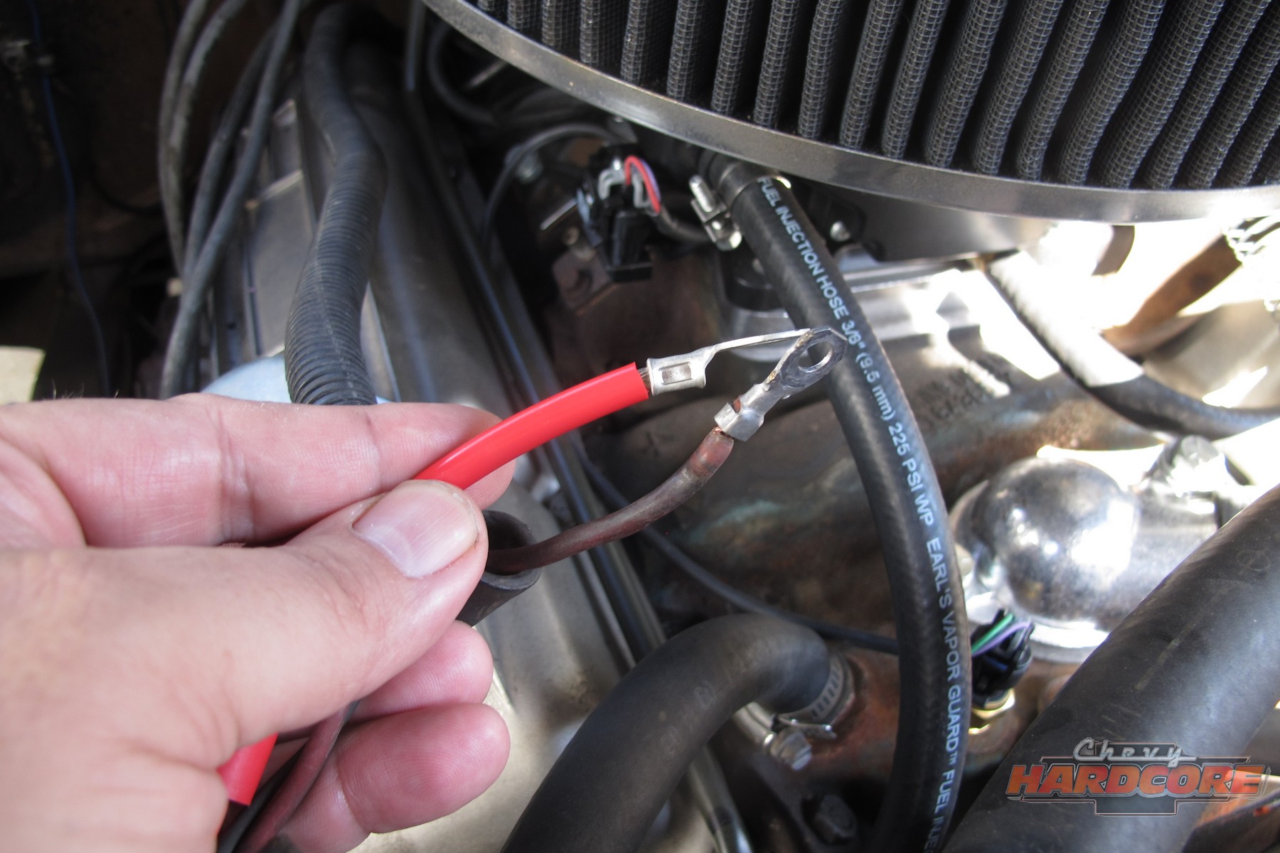
and connect the red wire to the output side of the alternator 10/32 stud, take the long wire and connect to the + side of the coil. If you are using a coil with external ballast resistor connect this wire to the battery side or key switch side of How To Wire Alternator 12-VOLT NEGATIVE GROUND 3 WIRE INSTRUCTIONS www.vintageautogarage.com
reconnect alternator wires and battery ground cable. If installing a 1-wire alternator, ... Note that our 1-wire alternators 7068, 7127, 7139 and 7140.2 pages
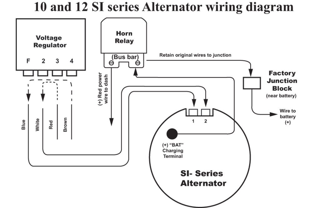
Common Delco SI Series Alternator Wiring Diagram. by David Smith Sep 22, 2016. We are commonly asked how to wire the Delco SI series alternators upon maintenance or upgrading from an older generator. While this series of unit often runs as a self exciting one wire, agricultural applications also used 3 wire connections to the alternator.
Wiring is easy, if you take a few minutes on google you can easily understand a GM 3-wire alternator. Step 1) do your research. step 2) go to auto parts store, get the following: a) alternator. b) electrical pigtail for the [1 2] connector on the back of the alternator. c) 12volt 1 amp (or higher) diode or 10 ohm resistor or idiot light to tie ...
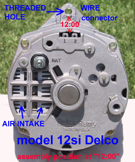
7127-9. 7127-9. Skip to the end of the images gallery. Skip to the beginning of the images gallery. Description. DELCO 10SI 63A 12V IREF 1V. • 9:00 PLUG LOCATION. Applications. AUTOMOTIVE & INDUSTRIAL APPLICATIONS.
Using the alternator in either instance requires no extra effort on the part of the end user. If you want to use it as a one wire, connect the charge wire to the battery and alternator and you're done. If you wish to use the three-wire system, connect the charge wire, remove the black plug at the two-wire terminal location and plug in your ...

7127 Alternator Wiring Diagram. Remove the voltage regulator plug connector from the original alternator. 4. For Delco applications without tachometer, use wiring harness adapter P/N ( universal .. 63 ALN. 63 ALN. 63 ALN. Product Code: SEN.
Jun 3, 2013 — Wire 10si 7127 Se Delco Alternator Alternator New Delco Alternator. Delco Remy Alternator Wiring Diagram on Transistor Voltage Regulator And ...

7127 Alternator Wiring Diagram. 7127 Alternator Wiring Diagram from shop.advanceautoparts.com. Print the wiring diagram off plus use highlighters to trace the signal. When you make use of your finger or perhaps the actual circuit with your eyes, it is easy to mistrace the circuit. 1 trick that We 2 to printing a similar wiring plan off twice.

How to replace parts on Delco Remy Alternators.

150 Amp Alt. use 6 gauge up to 6ft. Alternator Ground: Many mounting brackets are powder/clear coated, painted, or plated.1 page
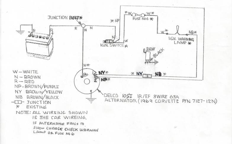
A DL-7127-9M. Attached photo shows the suggested wiring for this alternator. However,mine was not wired this way. I had the "Bat" terminal wired to the heavy yellow wire in the harness as the Centech instructions say. And, had a wire going from the positive battery terminal to the #2 terminal on the alternator.
If you jump the no.2 wire to the batt wire on the back of the alternator, it will work, but you are setting up a chronic low charge condition. The number 2 terminal is used to sense system voltage, and if it is seeing 12.5 volt at the alternator it shuts it down, when the rest of the system may be seeing only 11.8.

Cs144 Wiring Diagram- wiring diagram is a simplified up to standard pictorial representation of an electrical circuit.It shows the components of the circuit as simplified shapes, and the capacity and signal links between the devices. A wiring diagram usually gives counsel just about the relative twist and covenant of devices and terminals on the devices, to put up to in building or servicing ...
Dei 555l Wiring Diagram; Kinter Ma-150 Wiring Diagram; 7127 Alternator Wiring Diagram; Aaon Rn Series Wiring Diagram; Cub Cadet Lt1042 Belt Diagram; Ka24de Distributor Wiring Diagram; Diagramming The Scriptures; Sterling Gas Heater Wiring Diagram Qvf 75; Wiring Diagram For Reliance 606 Water Heater; 1620 Ford Tractor Wiring Diagram | Tricia Joy ...


0 Response to "40 7127 alternator wiring diagram"
Post a Comment