39 single wire alternator wiring diagram
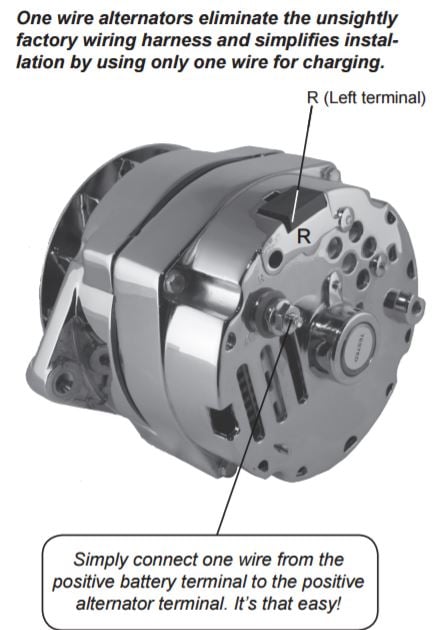
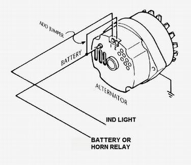
Self-Exciting Alternator makes no need for Alternator Wiring Diagram The Self-Exciting alternator is an alternator that has a special voltage regulator that doesn't need an ignition wire to activate it.This is usually based on a chevy alternator type and only requires a battery wire connected to the battery terminal.
The General Motors one-wire alternator needs to have only one wire connected to operate. This feature has made this unit popular with car enthusiasts and ...
One wire alternators eliminate the unsightly factory wiring harness and simplifies instal- lation by using only one wire for charging. NO WARNING LIGHT. Note ...1 page

Single wire alternator wiring diagram
Chevy One Wire Alternator Wiring - Wiring Diagram Detailed - One Wire Alternator Wiring Diagram. Wiring diagram also gives useful ideas for tasks which may need some added equipment. This book even includes suggestions for additional provides that you could want to be able to end your projects.
Single Wire Alternator Diagram - wiring diagram is a simplified conventional pictorial representation of an electrical circuit. It shows the components of the circuit as simplified shapes, and the capacity and signal friends together with the devices. A wiring diagram usually gives opinion approximately the relative incline and understanding ...
Connection diagram of the single phase induction generator scientific small sel generators wiring diagrams china 2p 100a wireswiring for transfer switches residential changeover switch 750kv mcr temperature rise test is a self regulated excited electerical engineering and tecnolgy manual portable 8 43 00 am 3 comments today i writing about as you know that ac principle construction working ...
Single wire alternator wiring diagram.
Changing the pulley ratio on the alternator by slowing it down will generally keep a one-wire regulator from charging. This can also produce a low voltage problem at engine idle speed depending on the amount of reduction. Alternators are usually tested with a 3:1 pulley ratio. This is the recommended street pulley ratio and is used in most ...
Catalog. Gm delco type cs130 series alternator one wire wiring the cj2a external regulated 10dn catalog single mg scool me in page 4 ih8mud forum is a right remy cs121 serie 10si issues seaboard marine voltage regulator el help ford truck g questions hot changing from 2 to 1 chevy nova how do i 3 what are wires on an 21si amp 22si self studebaker ls conversion swap information remey 1947 ...
9 - If installing an alternator with OEM wiring connections, reconnect alternator wires and battery ground cable. If installing a 1-wire alternator, see wiring instructions at upper right. 10 - Make sure battery is fully charged before starting engine. 11 - Reconnect the ground cable, start the engine and using a VOM meter, verify that the ...
Alternator Wiring Diagram - Wiring Diagram is the visual representation of a intricate electric circuit. It represents the physical parts of the electrical circuit as geometric forms, with the real power and connection connections in between them as thin sides.
basic gm alternator wiring wiring diagram database. Architectural wiring diagrams feint the approximate locations and interconnections of receptacles, lighting, and surviving electrical services in a building. Interconnecting wire routes may be shown approximately, where particular receptacles or fixtures must be upon a common circuit.
Wiring Diagram for Alternator with External Regulator - wiring diagram is a simplified gratifying pictorial representation of an electrical circuit. It shows the components of the circuit as simplified shapes, and the gift and signal associates in the midst of the devices. A wiring diagram usually gives assistance about the relative approach ...
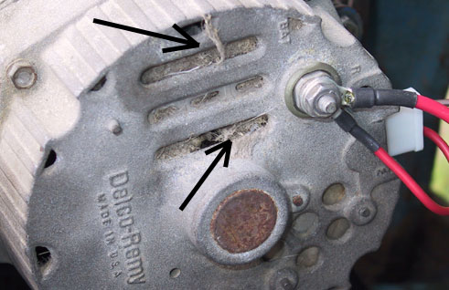
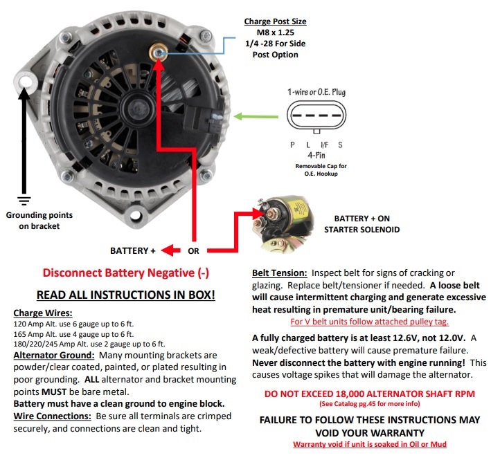
Alternator Ground: Many mounting brackets are ... alternator will not ground properly without a ground wire ... GM SI Alternator (One Wire or OE Hookup).1 page
Chevy single wire alternator wiring diagram. Most modules use an internal driver to turn the alternators field circuit on. Each component should be placed and connected with other parts in specific way. Gm Single Wire Alternator Diagram Wiring Diagrams Hubs One Wire Alternator Wiring Diagram Chevy.
Alternator Exciter Wiring Diagram - alternator exciter circuit diagram, alternator exciter wiring diagram, Every electrical arrangement is made up of various different pieces. Each part ought to be placed and linked to other parts in particular way. If not, the structure will not function as it ought to be.
reconnect alternator wires and battery ground cable. If installing a 1-wire alternator, see wiring instructions at upper right.2 pages
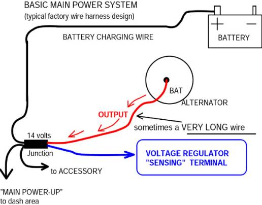
Understanding the Alternator • Four wires connect the alternator to the rest of the charging system. • B is the alternator output wire that supplies current to the battery. • IG is the ignition input that turns on the alternator/regulator assembly. • S is used by the regulator to monitor charging voltage at the battery.
Lucas 15 Acr Alternator Wiring Diagram - Wire Data Schema • - lucas 15 acr alternator wiring diagram ford 8n alternator rh banyan palace com Chevy Alternator Wiring Diagram Ford Alternator Wiring Diagram. Source. Hi I have a Lucas 18 ACR Alternator on a boat. The wiring was missing so I have connected one large terminal to the battery/starter ...
1 wire alternator wiring diagram - wiring forums in 2021 | 8n ford ...
(tach) wire if needed and other necessary wiring. Connect alternator to Balmar regulator wiring harness as indicated in wiring diagram included on Page 12. The alternator's positive and ground cables should be sized according to the chart on Page 3. 7. If a new regulator is being installed along with the alternator, complete its wiring ...

One wire alternator
Attached is a diagram for a 68 mustang. Many of the "basic connections" are identical as for your 73. lets start with the following explanation. Alternator: when the original alternator was removed. it had a harness attached that ended in a 3-position connector much like the one (14305 assy) shown on the diagram.
Powermaster one wire alternator hook up question | stangnet
Single Wire Alternator Wiring Diagram. Print the wiring diagram off plus use highlighters to trace the signal. When you make use of your finger or perhaps the actual circuit with your eyes, it is easy to mistrace the circuit. 1 trick that We 2 to printing a similar wiring plan off twice. Upon one, I'll trace the current movement, how it ...
How to hook up a single wire alternator | it still runs
15 May 2017 — Can anyone provide a link to a clear wiring diagram for a one wire alternator on a tractor with battery ignition. Tractor had been converted ...Need help on alternator wiring1 Apr 20171 Wire Alternator13 Jun 2017More results from farmallcub.com

17+ car alternator wiring diagram - car diagram - wiringg.net ...
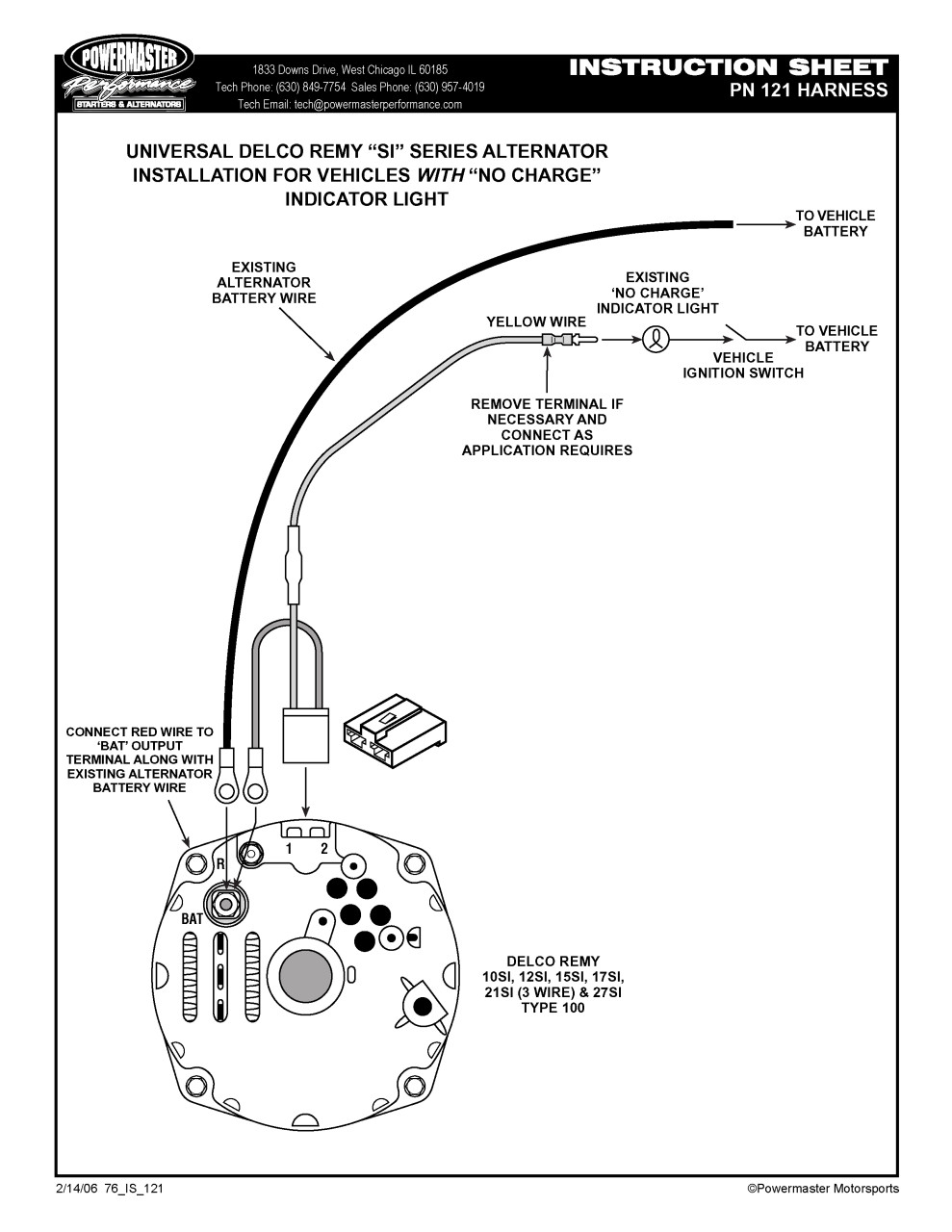
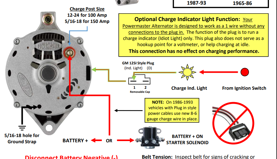
WIRING INSTRUCTIONS GM SI Alternator (One Wire or OE Hookup) Tech Dept. (630) 957-4019 Tech@powermasterperformance.com Replaces these OEM Alternators GM 10DN Externally Regulated GM 10SI Internally Optional Charge Indicator Light Function: Your Powermaster Alternator is designed to work as a 1 wire without any connections to the plug in. The
86 jd-950 changing alternator to a one wire system | green tractor ...
Alt Wire Diagram Alternator Wiring And Out The Dash Warning Light - 12 Volt Alternator Wiring Diagram. Wiring Diagram arrives with several easy to stick to Wiring Diagram Directions. It's supposed to assist all the typical user in developing a suitable method. These guidelines will likely be easy to grasp and apply.
1-wire alternator question - the 1947 - present chevrolet & gmc ...
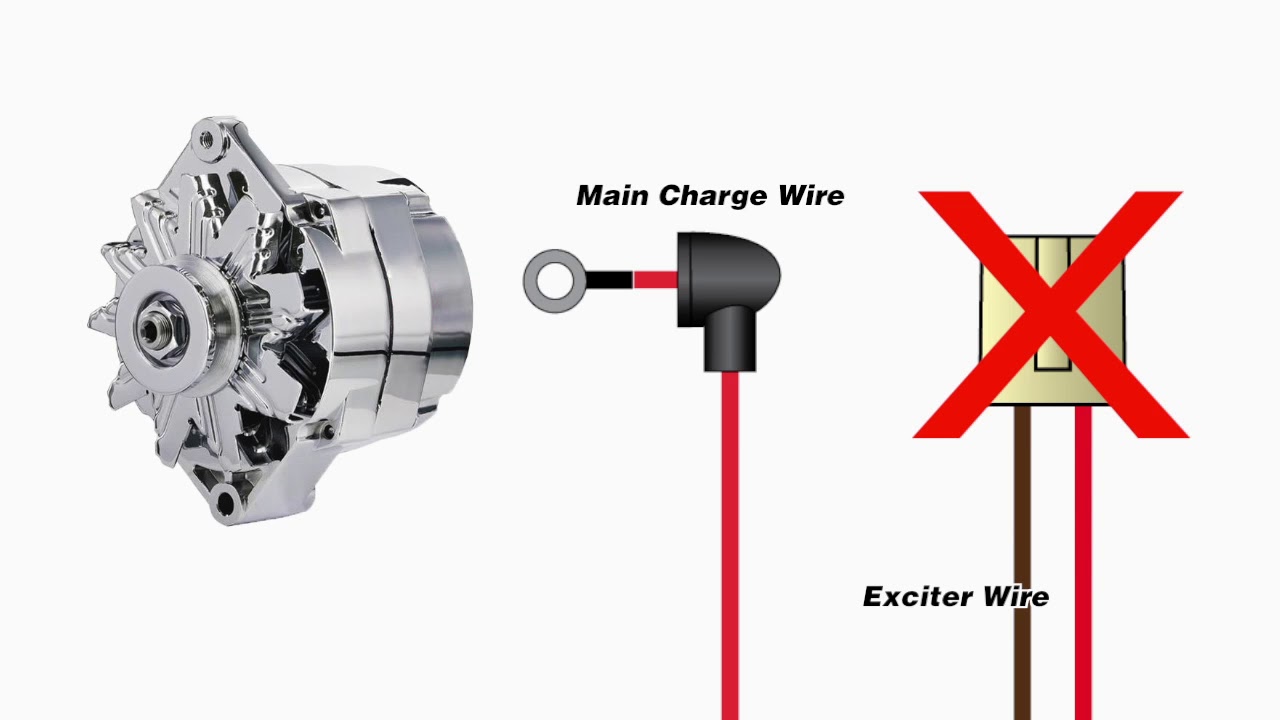
Single wire turn on alternators If your alternator comes with a pigtail that plugs into the alternator with a single loose wire coming out of it, this small exciter wire will need to be connected to an ignition switched source to turn the alternator on and off with the key switch.
Gm 1 wire 100 amp alternator upgrade and info diy
Motorcycle Voltage Regulator Schematic Diagram and Dnepr Voltage Regulator Wiring Diagram - Wiring Diagrams Folder - 15+ Motorcycle Voltage Regulator ...
1 vs 3 wire with painless performance and ron francis
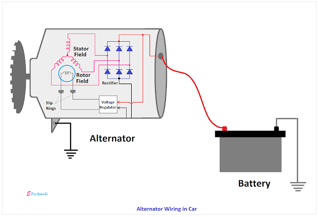
Below given are some alternator wiring diagrams that are used for different purposes.Let's have a look at their connections. 3 Wire Alternator Wiring Diagram Source: www.carparts.com This is a three-wire alternating wiring diagram showing the connections between the different components of a circuit.

Single wire alternator wiring diagram | alternator, car mechanic ...
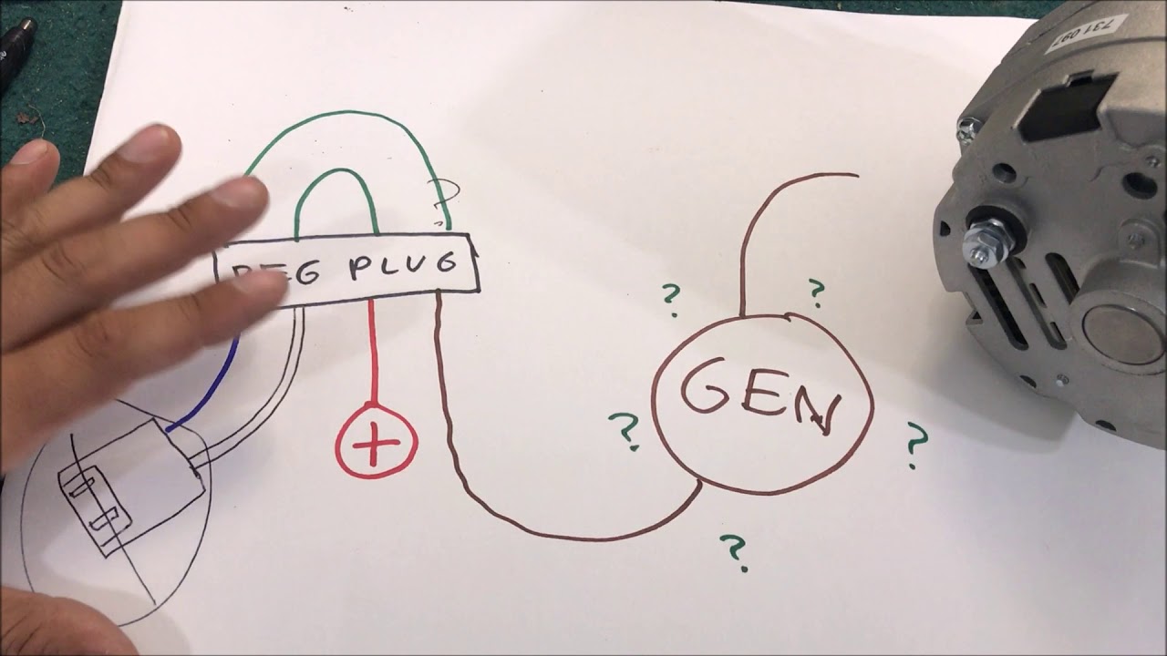
This video shows you how to wire a Single Wire Alternator on Tractors.We are showing this example on an MF 35 Deluxe Tractor but the same wiring will work on...

One wire alternator and u14 ammeter | team chevelle
April 15, 2020 · Wiring Diagram. by Anna R. Higginbotham. one wire alternator wiring diagram - You will need an extensive, professional, and easy to comprehend Wiring Diagram. With this kind of an illustrative guidebook, you'll have the ability to troubleshoot, stop, and total your projects easily.

One wire alternator - page 2 - farmall cub
Typical externally regulated alternator Wiring instructions for the early GM Delco Remy external regulated alternator. How to wire an external voltage regulator on a GM vehicle. The early GM alternator is the 10DN series alternator and was used on GM vehicles from about 1963-1970 Typical generator charging system Typical internally regulated ...
Powermaster 1 to 3 wire alternator wiring harness - vintage parts ...
21 Aug 2020 — Single wire alternators are utter simplicity from a wiring standpoint, one wire to the battery terminal and you're done. Down sides are that ...
Gm single wire alternator wiring : mg engine swaps forum : mg ...
Common Delco SI Series Alternator Wiring Diagram. by David Smith Sep 22, 2016. We are commonly asked how to wire the Delco SI series alternators upon maintenance or upgrading from an older generator. While this series of unit often runs as a self exciting one wire, agricultural applications also used 3 wire connections to the alternator.
One wire alternator problem - ford truck enthusiasts forums
Single Wire Alternator Wiring Diagram On Jn2Alt Jpg And Car, size: 800 x 600 px, source: carlplant.me. Whatever you are, we attempt to bring the material that matches exactly what you are trying to find. You might originate from an internet search engine, after that locate this web site. This subject is a lot of individuals browsing on the web ...

More generator alternator conversion.... 1-wire gm | the h.a.m.b.
Not only single wire alternator conversion diagram, you could also find another pics such as Chevy One Wire Alternator Wiring, GM 1-Wire Alternator, 2Wire Alternator Wiring Diagram, 2 Wire Alternator, and 10Si Alternator Wiring Diagram. Don't forget to bookmark single wire alternator conversion diagram using Ctrl + D (PC) or Command + D (macos).

Best way to hookup a 1 wire alternator ?? - the 1947 - present ...
A typical 3-wire alternator wiring diagram with an internal voltage regulator. Computer-Controlled Voltage Regulation. Many late-model vehicles use the engine computer, which is often referred to as the powertrain control module (PCM), to control alternator output. Most modules use an internal driver to turn the alternator's field circuit on ...
Alternator wiring diagram: a complete tutorial | edrawmax
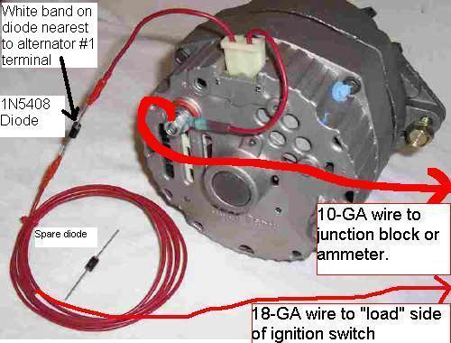
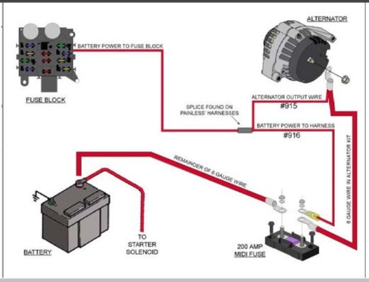
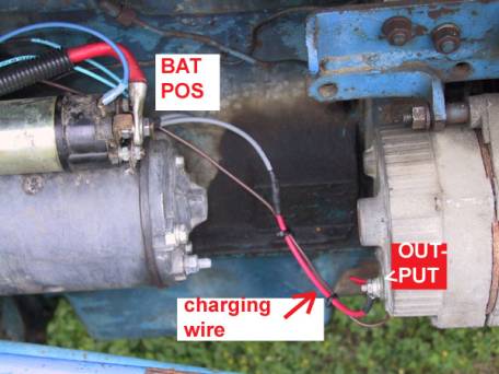
Note: the alternator charge wire routes direct to the battery and not through any switch connection, the alternator will not operate correctly if not connected direct to battery or directly through the ammeter. Note: the wiring that comes with our kits should be used as it is sized to handle the amperage.
One wire alternator warning light
Catalog
3-wire setup for driver's side alternator | team camaro tech

Google | alternator, car alternator, chevy
Changing from 2 wire alternator to 1 wire..question | the h.a.m.b.

One wire alternator - page 2 - farmall cub
How do i wire a gm 3 wire alternator | the h.a.m.b.

One wire alternator wiring - the cj2a page forums - page 1

Alternator wiring diagram: a complete tutorial | edrawmax
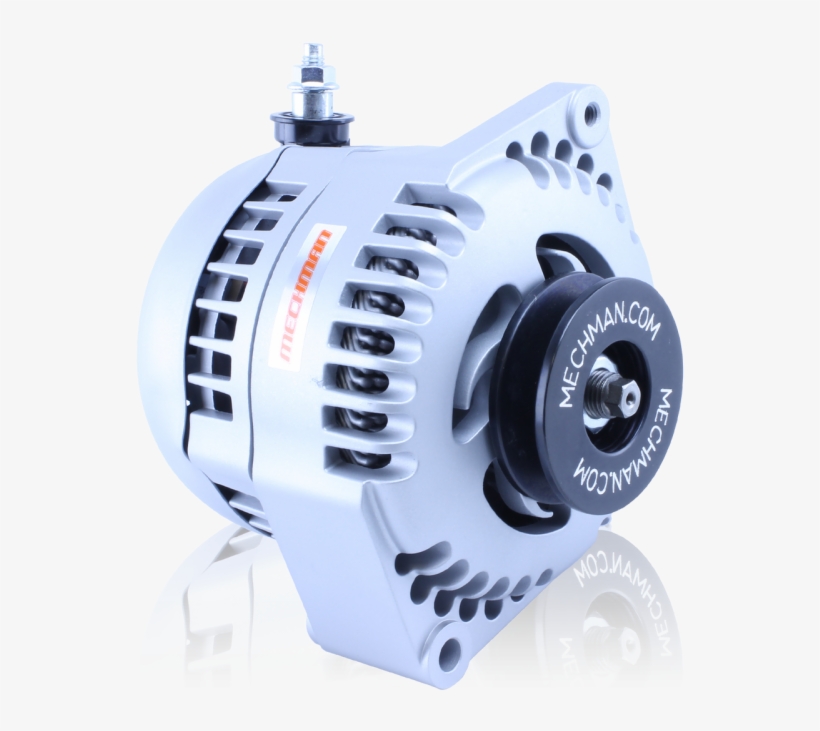
Mechman s series 170 amp racing alternator - mechman single wire ...

1-wire 6 volt alternator hookup - studebaker drivers club forum

Two minute tech : convert a 2-wire alternator to single wire ...
Catalog
Alternator wiring help please | chevy nova forum
1973 f250 one-wire alternator wiring help - ford truck enthusiasts ...
Catalog
One-wire alternators: are they better or just easier to hook up?

1 wire alternator round 2 - farmall cub

360620 chrome plated 100a gm 1/3 wire alternator
Dirty dingo motorsports - pages - ls conversion swap information
0 Response to "39 single wire alternator wiring diagram"
Post a Comment