38 draw a free-body diagram of the ball during the pitch. the ball is moving to the right.
The free-body diagram for the moving ball is given in Figure 4. Since the ball moves in a horizontal circle, its acceleration is horizontal. It is convenient therefore to use coordinates that are horizontal and vertical, and in the force diagram F string has been resolved into its horizontal and vertical components. Academia.edu is a platform for academics to share research papers.
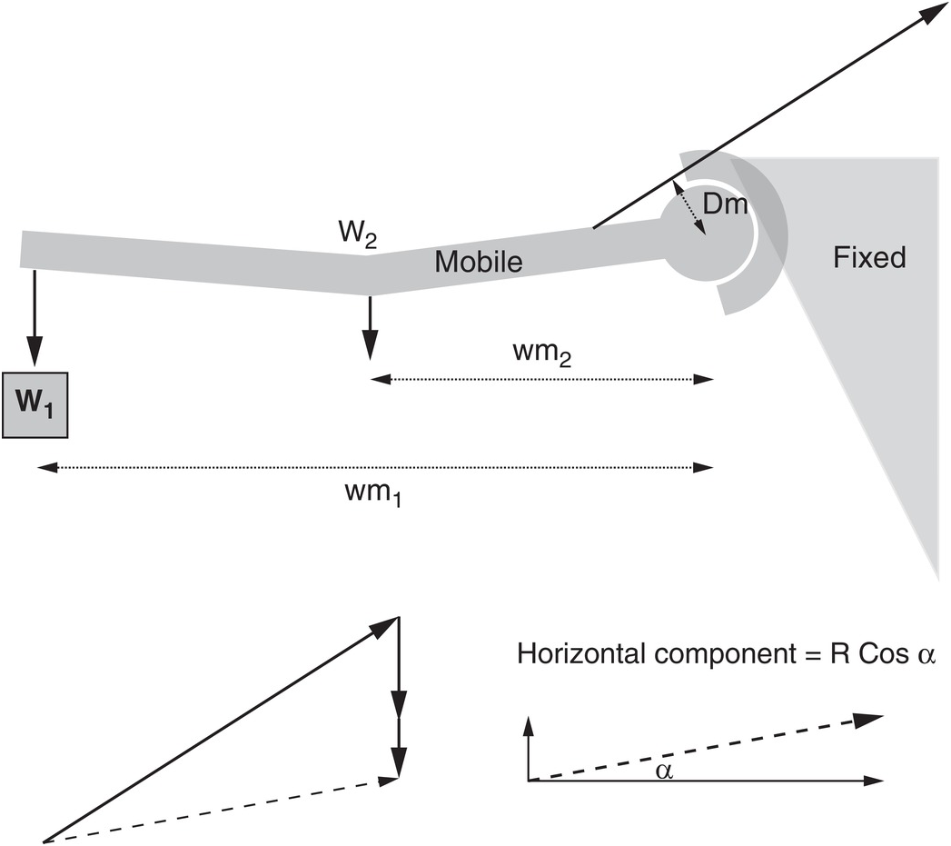
Radiation = added inertia (added mass) associated with hydrodynamic radiation in pitch . d) Use the head to tail method to draw the resultant. Vector Word Problems ~ach problem dr"aw and label a diagram, then solve. Left: water surface covered by natural slick, wind 1. 9: pg 30 q 42. Draw a picture of the angle that represents directly east. An airplane ying due east at 500 mph …

Draw a free-body diagram of the ball during the pitch. the ball is moving to the right.
Assuming the ball travels in a vertical plane, Calculate the a] Maximum height b] Time of flight and c] Horizontal range [g = 9. The playing field is 300 feet long (100 yards) the each end zone is 30 feet deep (10 yards). lincoln. Example 2 Thinking Skill Add: . if the football is kicked at the same speed, what other angle will allow the football - 715…. (A) 0. 0 m straight downfield. Click ... No, it could be moving backward and you would be reducing that velocity. 13. Free-Body Diagram Draw a free-body dia-gram of a water bucket being lifted by a rope at a decreasing speed. Specifically identify the system. Label all forces with their agents and make the arrows the correct lengths. Frope on bucket FEarth's mass on bucket System a ... The Doppler effect is observed whenever the speed of a sound source is moving slower than the speed of the waves.It leads to an apparent upward shift in pitch when the observer and the source are approaching and an apparent downward shift in pitch when the observer and the source are receding. But if the source actually moves at the same speed as or faster than the wave itself can move, a ...
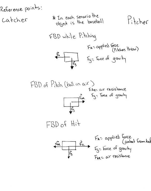
Draw a free-body diagram of the ball during the pitch. the ball is moving to the right.. 11. A ball of mass 1.5 kg is moving in a circular path of radius r figure with a speed of 8 m/s. 10 m as shown in the (a) (b) (c) (d) Please state which force keeps the ball in circular orbit Show all the forces acting on the ball along the direction. Show all the forces acting on the ball along the g direction. From part (b) and (c) find the ... In t-ball, young players use a bat to hit a stationary ball off a stand. The 140 g ball has about the same mass as a baseball, but it is larger and softer. In one hit, the ball leaves the bat at 12 m/s after being in contact with the bat for 2.0 ms . Assume constant acceleration during the hit. What is the net force on the ball during the hit? A solid uniform 45.0 kg ball of diameter 32.0 cm is supported against a vertical frictionless wall using a thin 30 cm wire of negligible mass. (a) Make a free body diagram for the ball and use it … to talk about this question, we need to draw a free body diagram for baseball when the the moment when it is hit by the bat. So if it is if it is hit by the bad, and this is, let's say, a ball of mass. M. Uh So the force which is the external force by hitting from the user, let's represented represented by F. And they will definitely be opposed due to the gravity, which is exactly downwards.
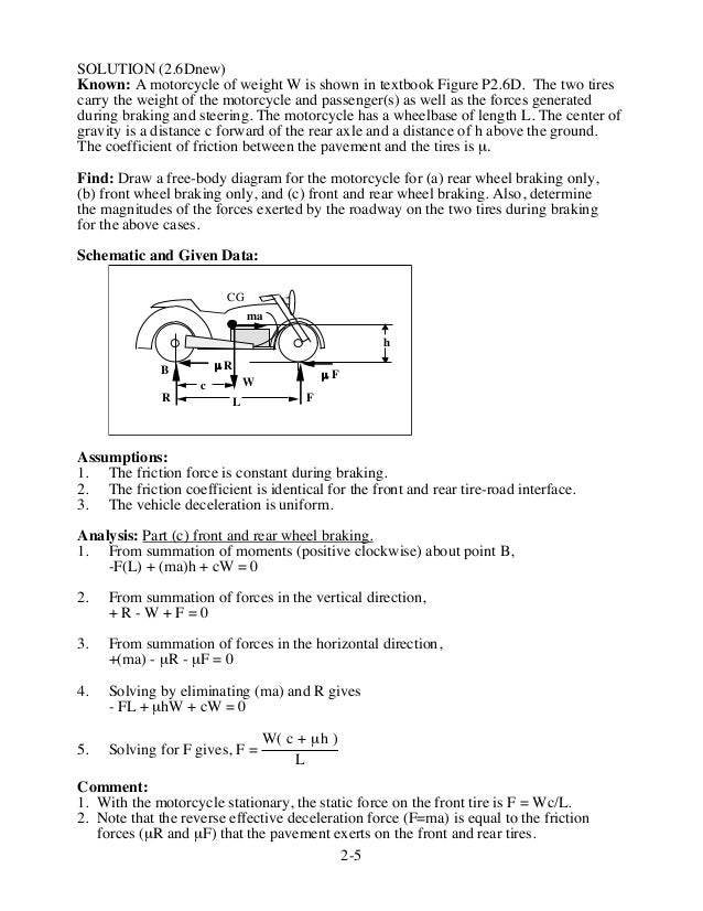
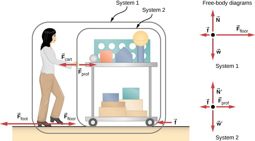
3. Draw a free-body diagram for each object identified in step 2. a. Assuming that the object can be modeled as a particle, you can represent it by a large dot. Do not include other objects (such as a surface the object may be rest-ing on or a rope pulling on it) in your free-body diagram. b. A. Draw a free-body diagram representing the raft for each situation. B. Find the force exerted by each lifeguard on the raft for each situation. (Disregard any other forces acting on the raft). A. F1 (220 N) and F2 (114 N) both point right; F1 (220 N) points left, and F2 (114 N) points right B. first situation: 220 N to the right, 114 N to the ... Academia.edu is a platform for academics to share research papers. Draw free body diagram of cylinder as shown in Fig. 2.10 ( a) Apply Principle of Transmissibility so that Reaction RB transmit to point ‘ O’ as shown in Fig. 2.10 ( b) (iii) Draw skeleton of forces as shown in Fig. 2.10 ( c) (iv) Now Fig. 2.10 ( c) represents concurrent coplanar force system which can be analyzed by two methods: A 20° 20° T B B O 240 kN Fig. 2.10 90° 70° O RB 240 kN ...
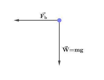
and F = 18.0 N. Draw a separate free-body diagram for each block and find (a) the acceleration of the blocks, (b) the resultant force on each block, and (c) the magnitudes of the contact forces between the blocks. 4) The assembly in the Right Figure is used to calculate the acceleration of a given system. An observer on the diagram the motion of the golf ball. v. 1st case: 9.0 s. v 2nd case: v v. The balls velocity simply decreased in the first case. In the second case, the ball slowed to a stop and then began rolling back down the hill. v v0 at 30.0 km/h (12.6(km/h)/s)(6.8 s) 27. A race car traveling at 44 m/s slows at a constant rate to a velocity of 22 m/s over ... If I let go of this ball, it flies out of the circle. Won't it go flying off this way? And no, it won't. If you let go of the string right now, for some reason the string broke, at this moment this ball would not veer off that way. There's no force pushing it to the right. The ball, if the string broke, would just follow Newton's first law. Draw a free-body diagram of the ball during the pitch. The ball is moving to the right. Draw the vectors starting at the black dot. (black dot is in the center) Must use these vectors on free body diagram: normal force, force on ball by pitcher, and weight.
A) Draw a free-body diagram of the ball during the pitch. The ball is moving to the right. B) What force did the pitcher exert on the ball during; Question: The fastest pitched baseball was clocked at 47 m/s. Assume that the pitcher exerted his force (assumed to be horizontal and constant) over a distance of 1.0 m, and a baseball has a mass of ...
Free-body diagram for crate just before ... /n=0.40 on x-axis on y-yönünde So the kinetic coefficient of friction: Free-body diagram for crate moving at constant speed +6.1. Friction Example:3 In example 2 suppose you move the crate by pulling upward on the rope at an angle of above the horizontal. How hard must you pull to keep it moving ...

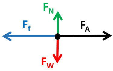
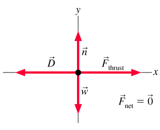
There are four forces acting upon the object as shown in the free-body diagram at the right. The two vertical forces must balance since there is no vertical acceleration. Since the mass and the acceleration are known, the net force can be computed: F net = m•a = (3.25 kg, right) • (1.20 m/s/s) = 3.90 N, right
A student draws the flawed free-body diagram shown in Figure P4.52 to represent the forces acting on a golf ball that is traveling upward and to the right a very short time after being hit off the tee. Air resistance is assumed to be relevant. Identify the errors in the diagram, then draw a correct free-body diagram for this situation.

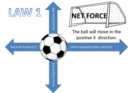
Drawing Free-Body Diagrams. Free-body diagrams are diagrams used to show the relative magnitude and direction of all forces acting upon an object in a given situation. A free-body diagram is a special example of the vector diagrams that were discussed in an earlier unit. These diagrams will be used throughout our study of physics.
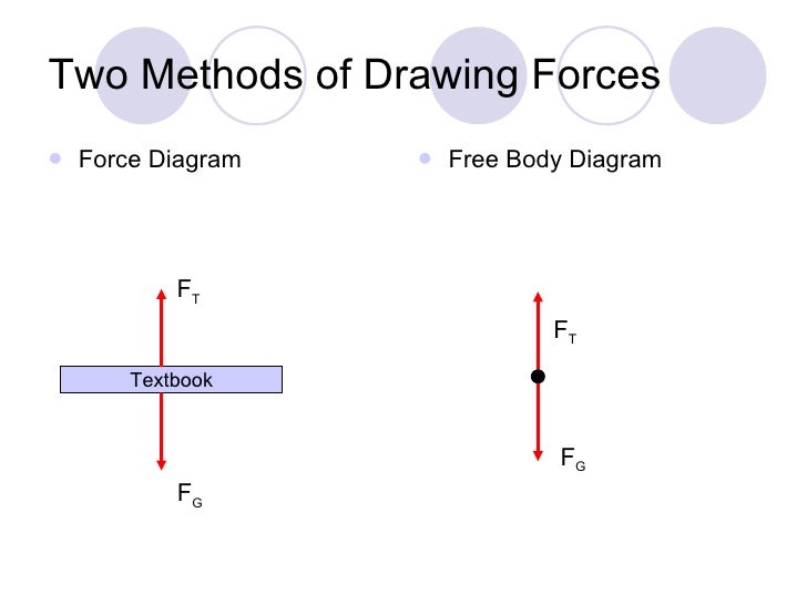
Figure 5.32 (a) The free-body diagram for isolated object A. (b) The free-body diagram for isolated object B. Comparing the two drawings, we see that friction acts in the opposite direction in the two figures. Because object A experiences a force that tends to pull it to the right, friction must act to the left. Because object B experiences a component of its weight that pulls it to the left ...
7. (yf05-059) A solid uniform 45.0-kg ball of diameter 32.0 cm is supported against a vertical, frictionless wall using a thin 30.0-cm wire of negligible mass, as shown in Fig. P5.59. (a) (With the help of a free-body diagram) Find the tension in the wire. (b) How hard does the ball push against the wall? Answer (a) 470 N (b) 163 N

21.05.2018 · (a) Draw a free-body diagram for the skier in Problem 32. (b) Determine the normal force acting on the skier. Solution: Chapter 5 Newton’s Laws Of Motion Q.46P · A 9.3-kg child sits in a 3.7-kg high chair. (a) Draw a free-body diagram for the child, and find the normal force exerted by the chair on the child. (b) Draw a free-body diagram for ...
Examples of drawing free-body diagrams. To better understand how to draw free-body diagrams using the 3 steps, let's go through several examples. Example 1. A box is pushed up an incline with friction which makes an angle of 20 ° with the horizontal. Let's draw the free-body diagram of the box. The first step is to sketch what is happening:
To draw a free body diagram, start by sketching a simple representation of the body you want to make the diagram of, like a square to represent a box. Next, draw arrows on the shape that show the forces acting on the object. For example, draw a downward arrow to signify the weight of the object, since gravity pulls the object down.
(a) Draw a freebody diagram for the top mass. (b) Draw a... Three identical 8.20 masses are hung by three identical springs. Each spring has a force constant of 7.10 and was 15.0 long before any masses were attached to it. Part A Draw a freebody diagram for the top mass.
as shown in the figure. The rope connecting the ball to the pole has length L 2.0 m. (a) (6) Draw a free-body diagram for the rotating tetherball. Be sure to label and indicate the direction of all forces acting on the ball. I cos 6

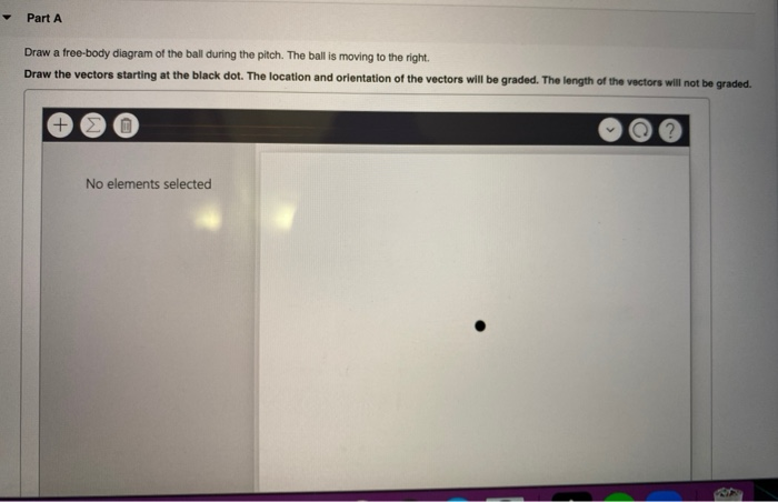
Draw a free-body diagram of the ball during the pitch. The ball is moving to the right. Draw the vectors starting at the black dot. The location and orientation of the vectors will be graded. The length of the vectors will not be graded.
STT 15.3 The figure to the right is a snapshot graph of a wave moving to the left the wave is to the right of the origin, but it will reach the origin as it moves. construct a history graph for the motion of the marked point at the origin following the approach shown in figure 15.7.

Free-body diagram – illustration 2.1. In order to determine support reaction forces, the free-body diagram of the entire structural system has been drawn in Figure 2.8. For this, the supports at A and B have replaced with the upward reaction R A and R B respectively, balancing the downward load of 2T. We know that moment at A is equivalent to ...
(a) Draw free-body diagrams of both objects. If the incline is frictionless and if m 1 = 5.00 kg, m 2 = 10.00 kg, and q = 60.0 °, find (b) the accelerations of the objects, (c) the tension in the string, and (d) the speed of each object 2.00 s after being released from rest. (a) Free Body Diagram (b) sin 60 ° = F in dir /100 N

Explain why an aluminum ball and a steel ball of similar size and shape, dropped from the same height, reach the ... Joanne is correct. The force to the right means that the acceleration is to the right. If it is moving to the right it is speeding up; if moving to the left it is slowing down. ... If you draw a free-body diagram for any point on ...

Figure 5.32 (a) The free-body diagram for isolated object A. (b) The free-body diagram for isolated object B. Comparing the two drawings, we see that friction acts in the opposite direction in the two figures. Because object A experiences a force that tends to pull it to the right, friction must act to the left. Because object B experiences a component of its weight that pulls it to the left ...
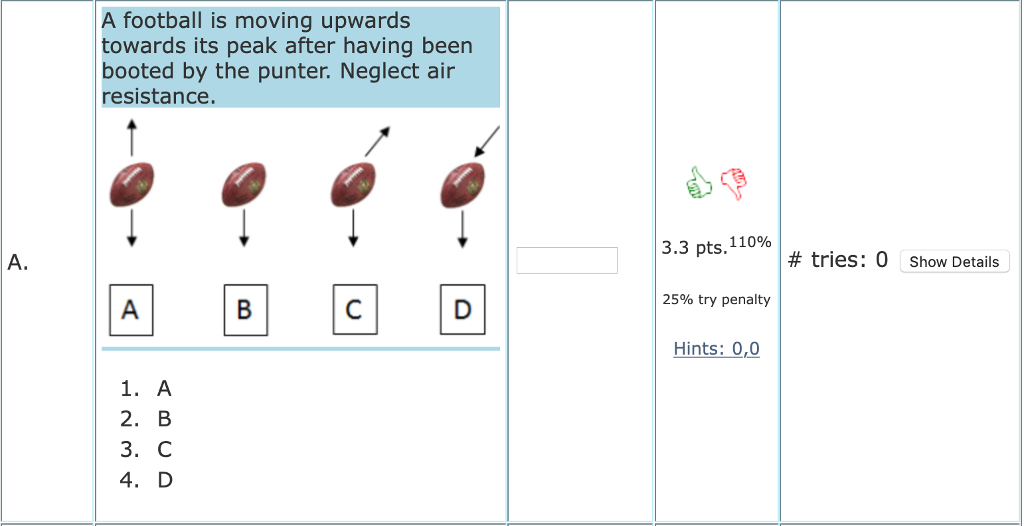
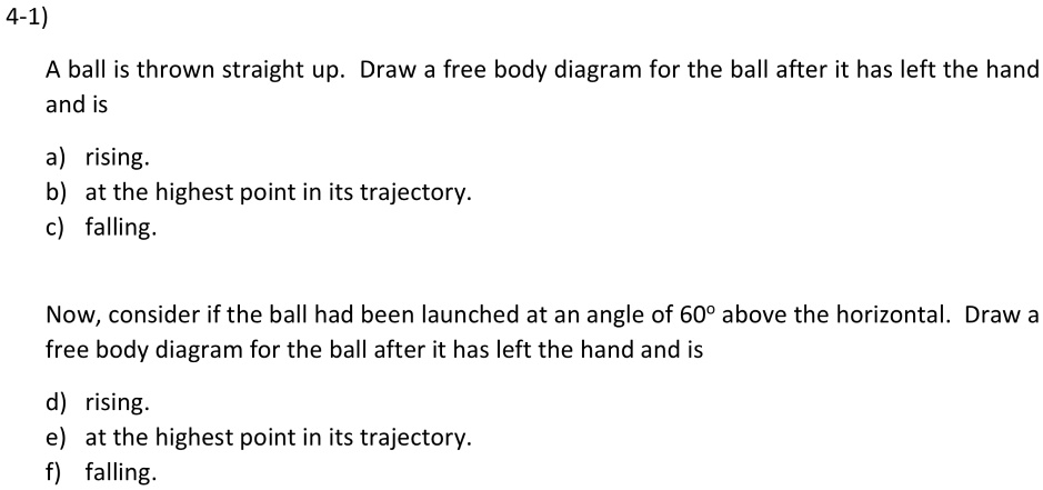
ball (more mass) is larger, its terminal velocity is larger, and it strikes the ground first a. b. C. Draw a free-body diagram for the ball at three points during its motion: on the way up, at the very top, and on the way down. Specifically identify the forces acting on the ball and their agents. On the way up FEarth's mass on ball At the top
arm forward during a pitch, rotating the forearm about the elbow. If the velocity of the ball in the pitcher's hand is 35.0 m/s (78.4 mph) and the ball is 0.300 m from the elbow joint, what is the angular velocity of the forearm?
The Doppler effect is observed whenever the speed of a sound source is moving slower than the speed of the waves.It leads to an apparent upward shift in pitch when the observer and the source are approaching and an apparent downward shift in pitch when the observer and the source are receding. But if the source actually moves at the same speed as or faster than the wave itself can move, a ...
No, it could be moving backward and you would be reducing that velocity. 13. Free-Body Diagram Draw a free-body dia-gram of a water bucket being lifted by a rope at a decreasing speed. Specifically identify the system. Label all forces with their agents and make the arrows the correct lengths. Frope on bucket FEarth's mass on bucket System a ...
Assuming the ball travels in a vertical plane, Calculate the a] Maximum height b] Time of flight and c] Horizontal range [g = 9. The playing field is 300 feet long (100 yards) the each end zone is 30 feet deep (10 yards). lincoln. Example 2 Thinking Skill Add: . if the football is kicked at the same speed, what other angle will allow the football - 715…. (A) 0. 0 m straight downfield. Click ...


0 Response to "38 draw a free-body diagram of the ball during the pitch. the ball is moving to the right."
Post a Comment