37 shear and moment diagram examples
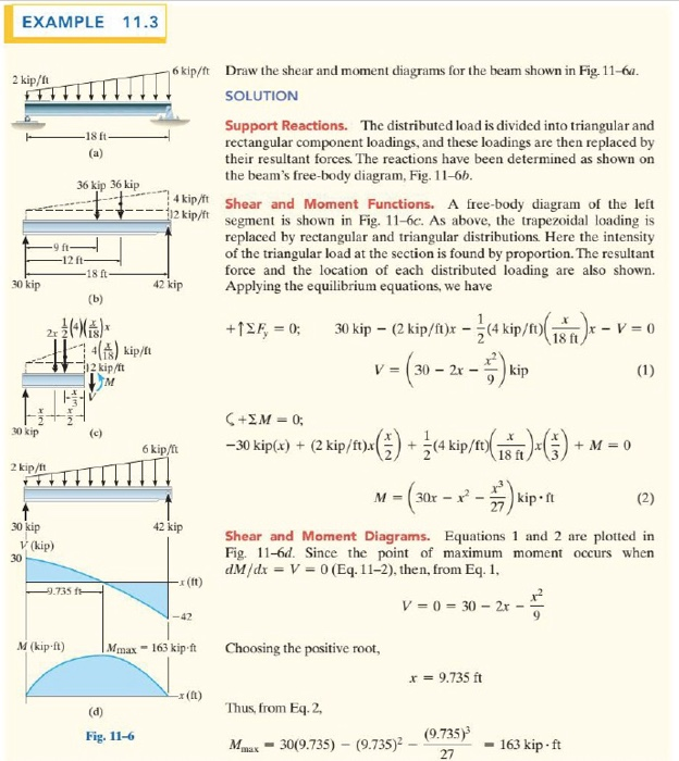
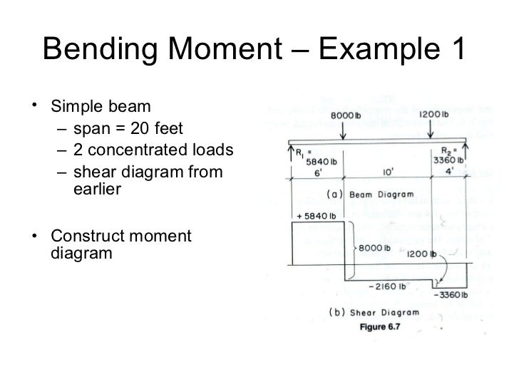
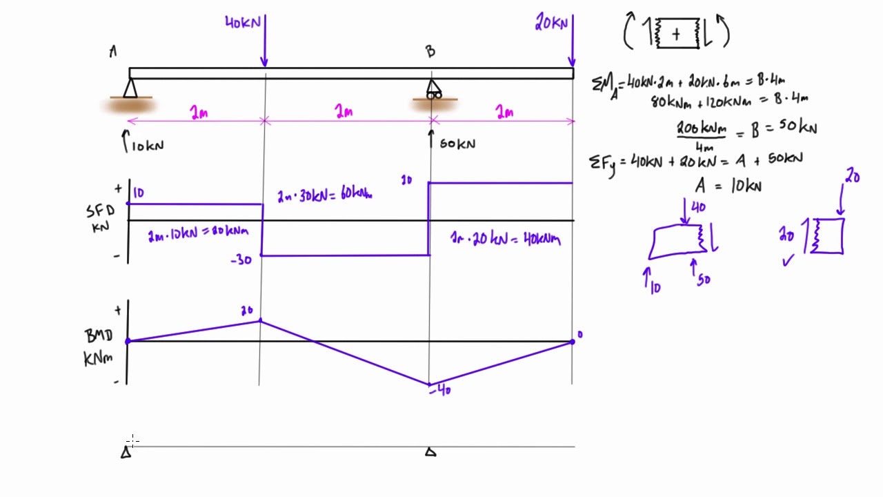
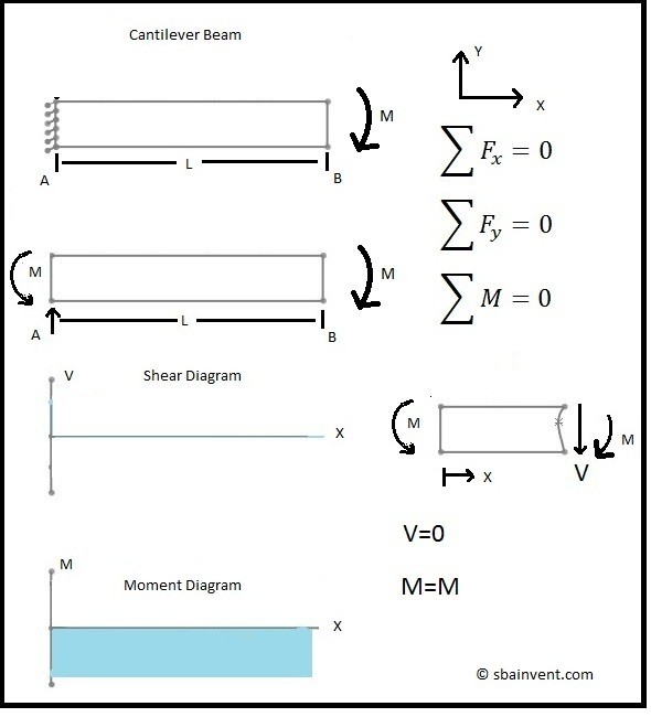
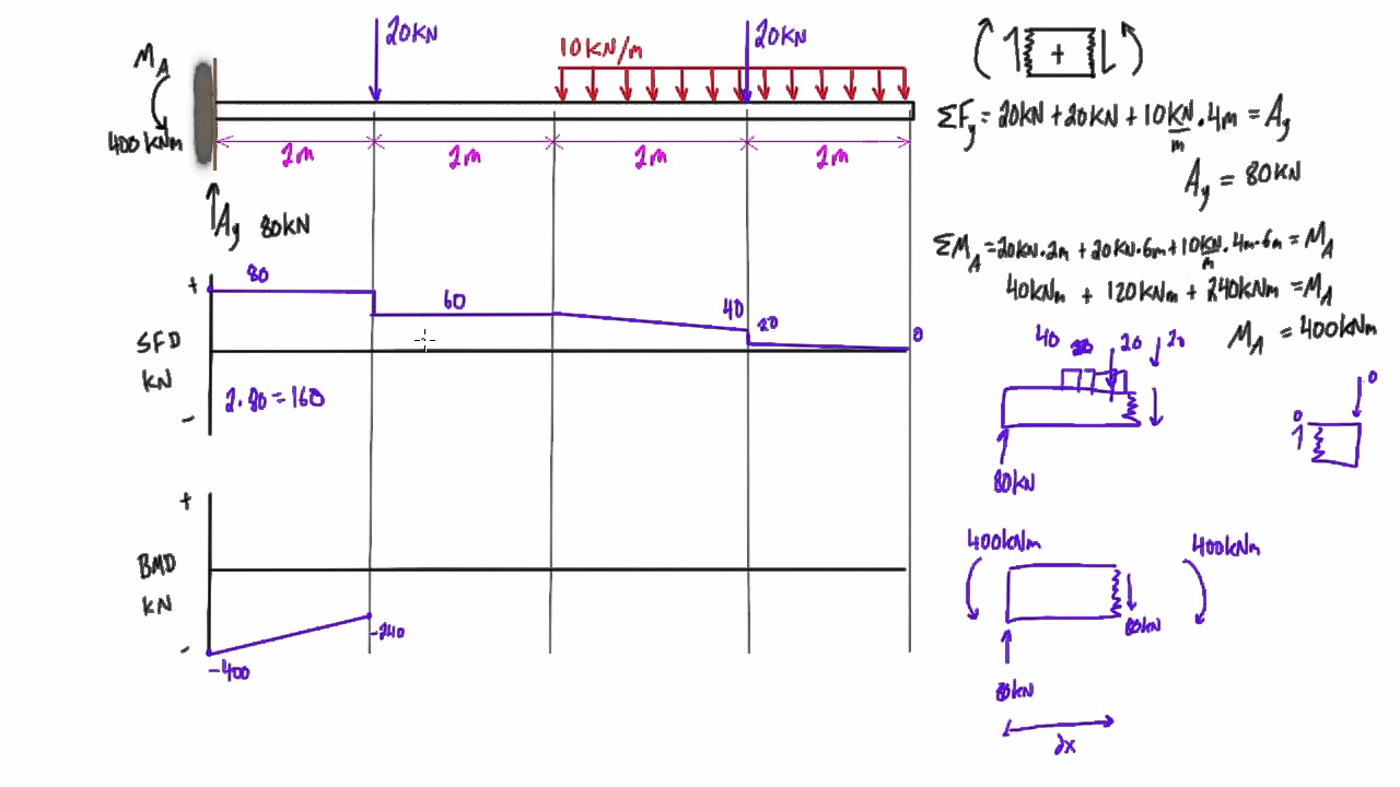
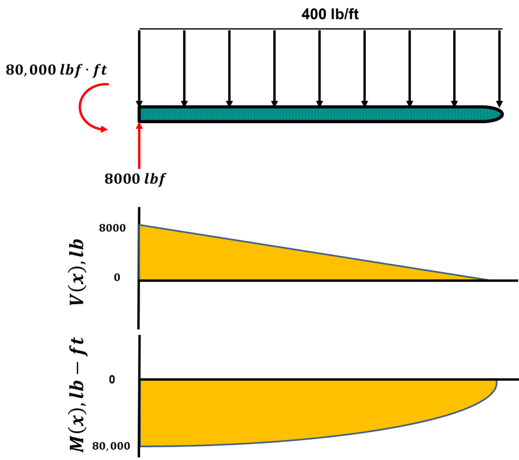
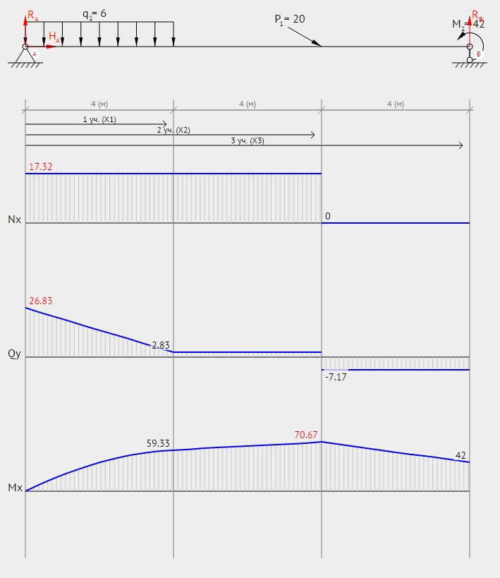
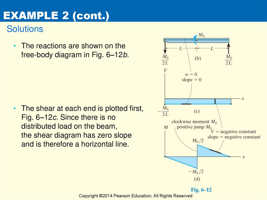
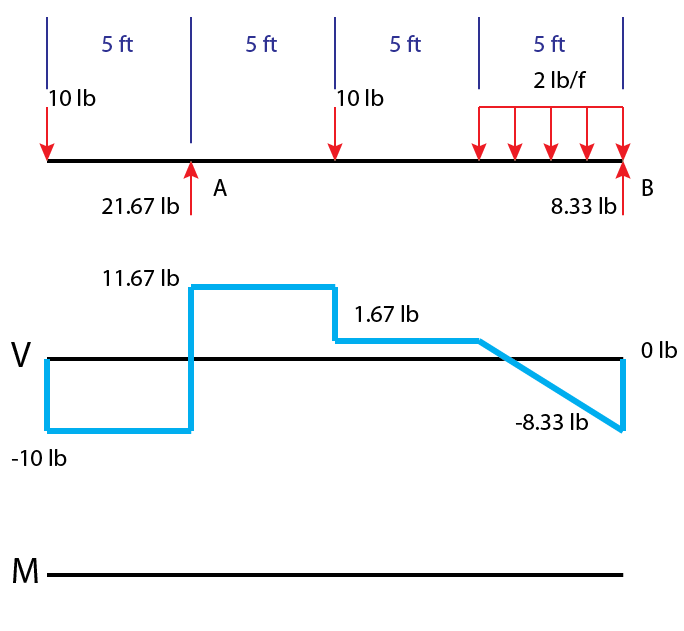
Jul 23, 2021 · Similarly to equation (23), this expressions allows us to infer a qualitative shape for the bending moment diagram, based on the shear force diagram we’ve already calculated. Consider the shear force between A and D for example; it’s constant, which means the slope of the bending moment diagram is also constant (an inclined straight line). Example 1. A simply supported beam is loaded as shown in the diagram. Calculate the support reactions and draw the Bending Moment diagram, Shear Force Diagram, Axial Force Diagram. Determine the maximum bending moment.
bending moment: kNm; shear: kN; 1 N/mm = 1 kN/m; 1 N/mm 2 = 10 3 kN/m 2; 1 kNm = 10 6 Nmm; Latitude and Acceleration of Gravity. Acceleration of gravity varies with latitude - examples: Location Latitude Acceleration og Gravity (m/s 2) North Pole: 90° 0' 9.8321: Anchorage: 61° 10' 9.8218: Greenwich: 51° 29' 9.8119: Paris: 48° 50' 9.8094: Washington: 38° 53' 9.8011 : Panama: 8° 55' 9.7822 ...
Shear and moment diagram examples
StructurePoint, formerly the PCA Engineering Software Group, offers concrete design software programs updated to ACI 318-14 for concrete buildings, concrete structures and concrete tanks. Reinforced concrete structural software includes programs for column design (pcaColumn), beam design (pcaBeam), slab design (pcaSlab), wall design (pcaWall), mat design (pcaMats), foundation design, tank ... Finally, the longer the rod, the smaller the shear strain. So far, we've focused our attention on displacements and strain. To discuss the stress within a twisted rod we need to know how torque and stress relate. Since twist applies a shear strain, we expect that torque will apply a shear stress. The relationship between torque and shear stress ... Jasbir S. Arora, in Introduction to Optimum Design (Third Edition), 2012 Step 1: Project/Problem Description. A beam of rectangular cross-section is subjected to a bending moment M (N·m) and a maximum shear force V (N). The bending stress in the beam is calculated as σ=6M/bd 2 (Pa), and average shear stress is calculated as τ=3V/2bd (Pa), where b is the width and d is the depth of the …
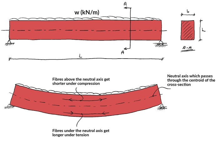
Shear and moment diagram examples. Design for Shear By Richard W. Furlong 2.1 Introduction Shear is the term assigned to forces that act perpendicular to the longitudinal axis of structural elements. Shear forces on beams are largest at the supports, and the shear force at any distance x from a support decreases by the amount of load between the support and the distance x. Under uniform loading, the slope of the shear diagram ... Dec 08, 2011 · From equation (2) it can be seen that if M is varying continuously, zero shearing force corresponds to either maximum or minimum bending moment. It can be seen from the examples that "peaks" in the bending moment diagram frequently occur at concentrated loads or reactions, and these are not given by ; although they may in fact represent the ... Mar 04, 2019 · The nominal shear is equal to the lateral forces on the retaining wall, neglecting the effect of passive pressure which will give us: Nominal Shear, V n = 20.05kN; Ultimate Shear, V u = 1.6Vn = 32.08kN; For the thickness of the wall to be safe in shear, the ultimate shear, V u should less than the allowable shear, V allow as recommended by the ... •Average shear stress: •Shear strain: •Shear modulus relates shear stress and strain: •Calculate shear modulus from Eand ν: •Direct shear: shear forces without bending moments or normal forces •Single vs. double shear •Pre-week videos: design of deformable materials, general states of stress, and axial deformation 12 W ave VA 2 ...
Bending moment at any height M=paxh/3= [ka h3]/6 ... Also check for shear at the junction. 4. Provide enough development length. 5. Provide the distribution steel. 26 Jasbir S. Arora, in Introduction to Optimum Design (Third Edition), 2012 Step 1: Project/Problem Description. A beam of rectangular cross-section is subjected to a bending moment M (N·m) and a maximum shear force V (N). The bending stress in the beam is calculated as σ=6M/bd 2 (Pa), and average shear stress is calculated as τ=3V/2bd (Pa), where b is the width and d is the depth of the … Finally, the longer the rod, the smaller the shear strain. So far, we've focused our attention on displacements and strain. To discuss the stress within a twisted rod we need to know how torque and stress relate. Since twist applies a shear strain, we expect that torque will apply a shear stress. The relationship between torque and shear stress ... StructurePoint, formerly the PCA Engineering Software Group, offers concrete design software programs updated to ACI 318-14 for concrete buildings, concrete structures and concrete tanks. Reinforced concrete structural software includes programs for column design (pcaColumn), beam design (pcaBeam), slab design (pcaSlab), wall design (pcaWall), mat design (pcaMats), foundation design, tank ...


0 Response to "37 shear and moment diagram examples"
Post a Comment