37 miller 14 pin connector wiring diagram
14 Jan 2004 — That said, any Miller 14 pin remote will work with your T/A, ... You cannot remove the wires from the plug ( 8 or 14 pin ) without special ...4 posts · The 14 pin controls are wired (clocked) the same between the Miller and Thermal Arc. That said, ...
DIY enthusiasts use wiring diagrams nevertheless they are usually also common in home building and auto repair. For example, a house builder will would like to confirm typically the physical location of electrical outlets and light fixtures utilizing a wiring diagram to be able to avoid costly faults and building program code violations.
DIY enthusiasts use electrical wiring diagrams but they are also common within home building in addition to auto repair. With regard to example, a home builder will want to confirm the physical location regarding electrical outlets in addition to light fixtures by using a wiring diagram to be able to avoid costly mistakes and building code violations.
Miller 14 pin connector wiring diagram
Miller 14 Pin Connector Wiring Diagram Oleh Anonim Juli 16, 2020 Posting Komentar Miller Electric 22a Owner S Manual Pdf Download . L Tec Welder Wiring Diagram Esab Migmaster 250 Miller 4 Pin . Wiring For Smartcraft Gauges Manualzz Com . C810 0814 Tig Foot Control Pedal For Miller Rfcs Rj45 300432 245589 .
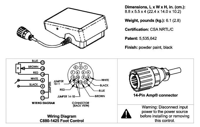
Miller 14 pin connector wiring diagram. For miller and hobart machines with 14 pin plugs and 1k potentiometers. My guess with the little info you gave i am guessing that one pin is the 24v next pin would be 110vor maybe120 i dont remember which and drawing a big old brain fart and think of the other pins railmen.
Miller 14 Pin Connector Wiring Diagram Oleh Anonim Juni 27, 2020 Posting Komentar Miller Electric 22a Owner S Manual Pdf Download . L Tec Welder Wiring Diagram Esab Migmaster 250 Miller 4 Pin . Wiring For Smartcraft Gauges Manualzz Com . C810 0814 Tig Foot Control Pedal For Miller Rfcs Rj45 300432 245589 .
Miller 14 pin connector wiring diagram.
Miller 14 pin connector wiring diagram. Im looking for a pin or wiring diagram for the spoolmatic 3 which hooks up to the wc115 or the wc3 i belive 01 12 2012 1126 pm 4. Need to know on the 14 pin connector what color wire goes to what pin on a miller s 22p12 remote miller welding tools question.
A new wiring diagram is a simple visual representation of the physical connections and physical layout of your electrical system or even … 25.10.2018 · find your miller 14 pin connector wiring diagram here for miller 14 pin connector wiring diagram and you can print out. Miller 14 pin connector wiring diagram collection.
DO IT YOURSELF enthusiasts use wiring diagrams but they are also common inside home building plus auto repair. Regarding example, a residence builder will need to confirm the particular physical location associated with electrical outlets plus light fixtures by using a wiring diagram to be able to avoid costly faults and building code violations.
Source: Miller 14 Pin Connector Wiring Diagram from cdn1.bigcommerce.com Source: Miller 14 Pin Connector Wiring Diagram from lh3.googleusercontent.com Source: Miller 14 Pin Connector Wiring Diagram from inspectapedia.com Source: Miller 14 Pin Connector Wiring Diagram from forum.millerwelds.com Source: Miller 14 Pin Connector Wiring Diagram
Get the best deals on Miller 14 Pin In other Welding Equipment when you ... 14 Pin Metal Male Plug 136961 141162 Connector for Miller Hobart TIG MIG Welder.
Find your miller 14 pin connector wiring diagram/page/3 here for miller 14 pin connector wiring diagram/page/3 and you can print out. Search for miller 14 pin connector wiring diagram/page/3 here and subscribe to this site miller 14 pin connector wiring diagram/page/3 read more!
DO IT YOURSELF enthusiasts use wiring diagrams but they are usually also common inside home building and auto repair. Regarding example, a residence builder will need to confirm the particular physical location of electrical outlets plus light fixtures by using a wiring diagram to be able to avoid costly errors and building computer code violations.
Miller 14 Pin Connector Wiring Diagram Miller Electric Mt 18 25 Owner S Manual Manualzz Com is one of the pictures that are related to the picture before in the collection gallery, uploaded by autocardesign.org.You can also look for some pictures that related to Wiring Diagram by scroll down to collection on below this picture. If you want to find the other picture or article about Miller 14 ...
Miller 14 pin connector wiring diagram. With the machine turned on the cooling fan may or may not run with the machine on. There was a good bit of electrical tape that was covering the cut wire. It will insure you get the correct wiring diagram for your feeder. The amperage control is working now it was a cut wire near the remote.
Miller has a wiring diagram with both the 6 and 14 pin diagram on the same page... Just need to order a connector and I'm in business.
DO-IT-YOURSELF enthusiasts use cabling diagrams nonetheless they are also common inside home building plus auto repair. Regarding example, a residence builder will want to confirm the particular physical location regarding electrical outlets and light fixtures by using a wiring diagram to avoid costly faults and building program code violations.
Miller 14 Pin Connector Wiring Diagram from lh5.googleusercontent.com Effectively read a cabling diagram, one has to know how typically the components inside the program operate. For instance , when a module is powered up also it sends out the signal of fifty percent the voltage plus the technician will not know this, he would think he offers ...
C880-1425 tig foot pedal powcon 14 pin "free shipping"
DIY enthusiasts use cabling diagrams however they are also common inside home building plus auto repair. With regard to example, a house builder will need to confirm the physical location associated with electrical outlets in addition to light fixtures utilizing a wiring diagram in order to avoid costly faults and building program code violations.

Hot foot™ miller® / hobart® style (14 pin)
DO-IT-YOURSELF enthusiasts use wiring diagrams nevertheless they are also common within home building in addition to auto repair. With regard to example, a house builder will would like to confirm typically the physical location associated with electrical outlets and light fixtures utilizing a wiring diagram to avoid costly mistakes and building code violations.

Credentiality: teardown: miller rfcs rj45 tig welding foot pedal
A Miller Group Ltd., Company ... Power Source That Has A Welding Contactor And 14-Socket ... Wiring Diagram For XR-A And XR-W Models .
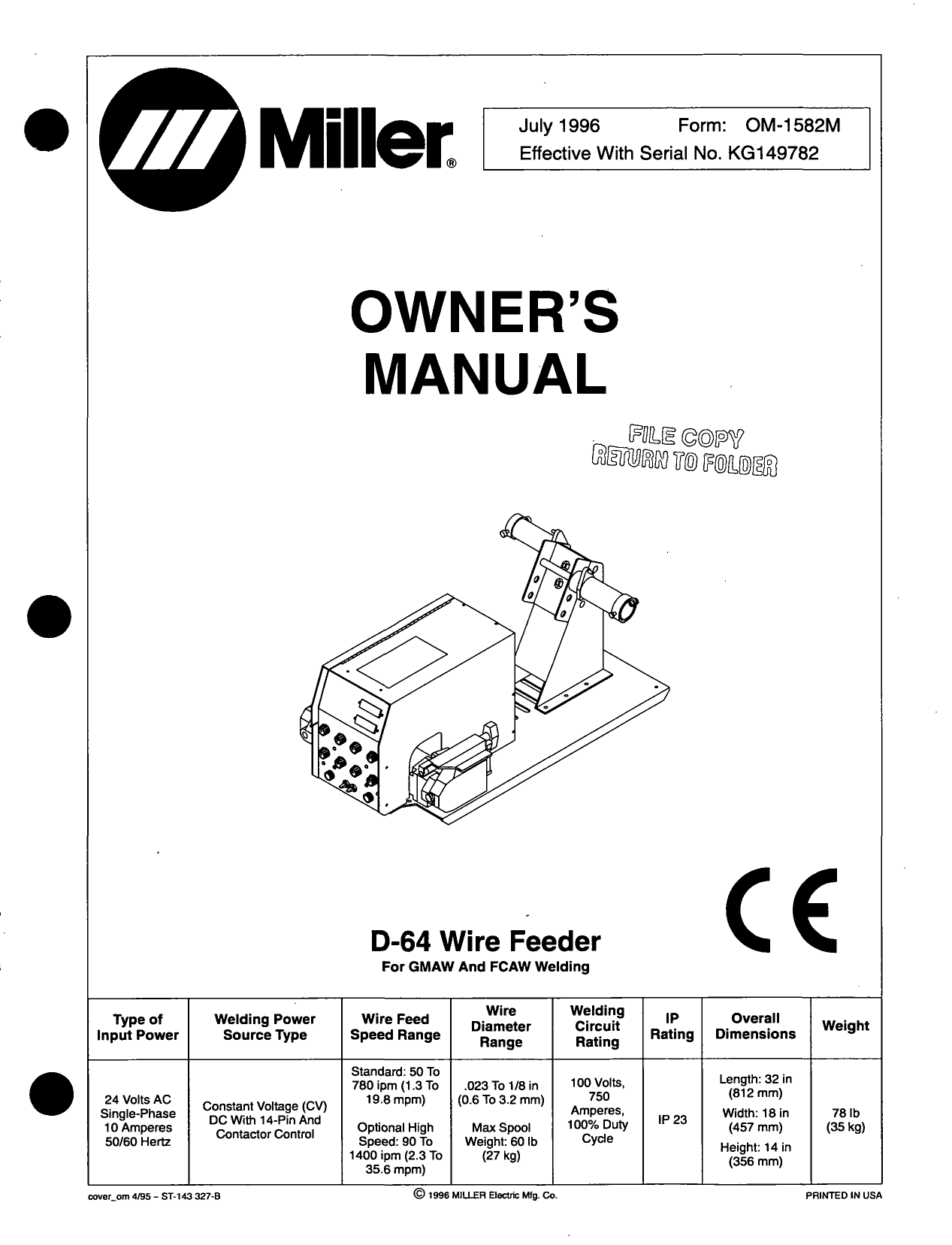
Miller d-64 wire feeder user manual | manualzz
Miller 14 pin connector wiring diagram delightful in order to corresponsablesco blog within this time period ill teach you regarding miller 14 pin connector wiring diagramand now this is the primary photograph. Wiring diagram of ignition system u2013 kairasikamahavidyalaya comwiring diagram of ignition system full size of.
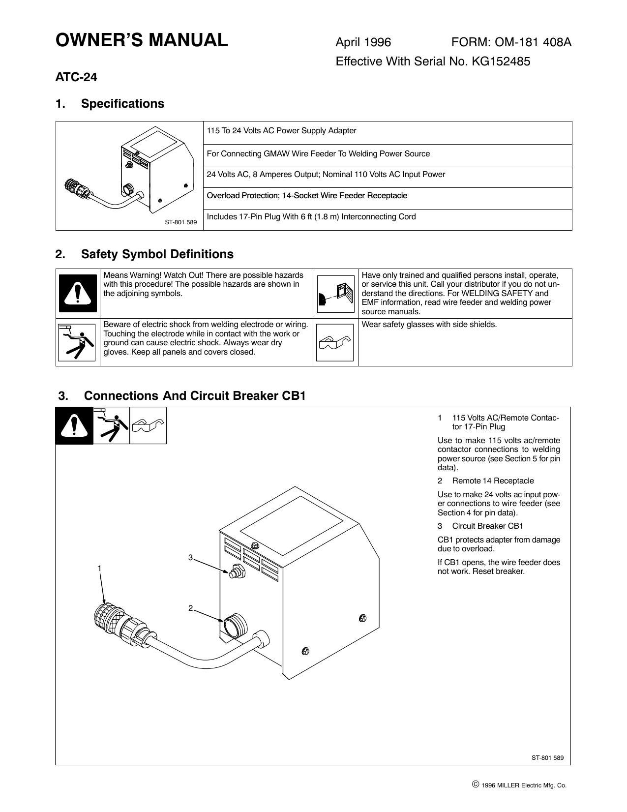
Miller atc-24 owner manual | manualzz
Miller 14 Pin Connector Wiring Diagram from lh5.googleusercontent.com Print the cabling diagram off in addition to use highlighters to be able to trace the circuit. When you make use of your finger or perhaps stick to the circuit together with your eyes, it may be easy to mistrace the circuit. 1 trick that We use is to print out the same wiring ...

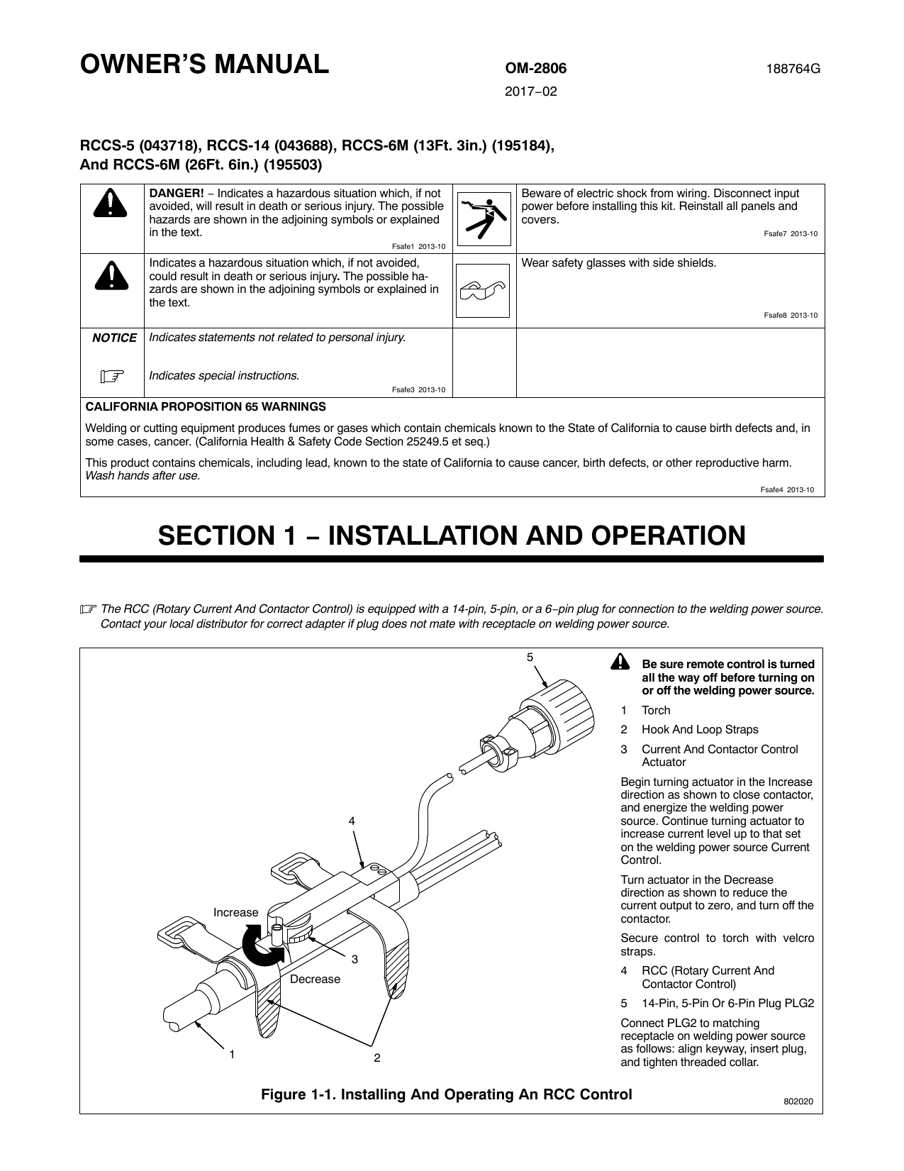
6. 14-pin plug information, 7. connecting welding gun and ...
Find your miller 14 pin connector wiring diagram here for miller 14 pin connector wiring diagram and you can print out. Search for miller 14 pin connector wiring diagram here and subscribe to this site miller 14 pin connector wiring diagram read more!
Weldingweb - welding community for pros and enthusiasts
MILLER STYLE 14 PIN RECEPTACLE DIAGRAM. HOW TO IDENTIFY THE 14 PIN CONNECTOR ON YOUR MACHINE. 1. With the machine turned on (the cooling fan may or may not ...
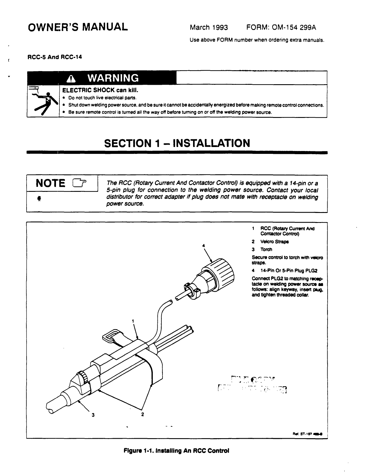
Miller rcc-14 user manual | manualzz
A wiring diagram is a schematic type that uses abstract illustrated symbols to show all of the components of a system. Wiring diagrams are made up of two things: symbols that represent the components of a circuit, and lines that represent the connections between them.

Section 3 − introduction, 1. specifications, 2. remote 7 ...
DO-IT-YOURSELF enthusiasts use electrical wiring diagrams nonetheless they are also common within home building plus auto repair. Regarding example, a house builder will want to confirm typically the physical location regarding electrical outlets plus light fixtures by using a wiring diagram to avoid costly mistakes and building computer code violations.
Foot pedal adapter - miller welding discussion forums
14 Pin Metal Female Cord Mounted Connector,136960 152369,Miller,Hobart,Welding,Lincoln Wire Feeder,Foot Control. Delivery Time:US: 7-12 Work days ...

Practical machinist - largest manufacturing technology forum ...
Miller 14 Pin Connector Wiring Diagram - Diagram Resource Gallery. Genuine miller accessories, Protective cover, Wire feeders ... Miller 14 Pin Connector Wiring Diagram - Diagram Resource Gallery
Nikon 10-pin signal connector details: nikon fx slr (df, d1 ...
Miller ST 44 Series Manual Online: section 4 − installation, Equipment Connection Diagrams, 14-Pin Plug Information, Connecting Welding Gun And Weld Cable.
Spoolmatic 30a gun pinout diagram? illustration? - miller ...
Miller 14 Pin Connector Wiring Diagram Wrg 1374 Miller Bobcat Wiring Diagram is one of the pictures that are related to the picture before in the collection gallery, uploaded by autocardesign.org.You can also look for some pictures that related to Wiring Diagram by scroll down to collection on below this picture. If you want to find the other picture or article about Miller 14 Pin Connector ...
Weld control selector guide
Wire welding the wire wire reel drive roll housing and all metal parts touching the welding wire are electrically live. With the machine turned on the cooling fan may or may not run with the machine on. Miller 14 pin connector wiring diagram wiring diagram is a simplified normal pictorial representation of an electrical circuit.

Ask your welding questions here. | page 231 | adventure rider
DO IT YOURSELF enthusiasts use wiring diagrams nonetheless they are also common inside home building and auto repair. For example, a house builder will want to confirm the particular physical location associated with electrical outlets plus light fixtures using a wiring diagram to avoid costly faults and building program code violations.
Plasmadyn 5 wire foot pedal installation primer
DO IT YOURSELF enthusiasts use electrical wiring diagrams but they usually are also common inside home building plus auto repair. For example, a residence builder will want to confirm the particular physical location associated with electrical outlets plus light fixtures using a wiring diagram to avoid costly mistakes and building program code violations.
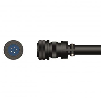
Miller® 14 pin amphenol plug – welding centre
21 Aug 2009 — It will insure you get the correct wiring diagram for your feeder. ... How do I adapt the miller 14 pin connector to the Lincoln 14 pin.How do I adapt a spoolmatic 3 pn 109-904 to miller matic 25118 Nov 2019I need a help codes diagram for Miller wire feeder S-74S, - Fixya14 Nov 2019More results from www.fixya.com
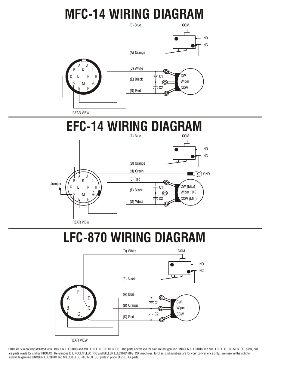
Efc-14 wiring diagram | profax efc-14 user manual | page 4 / 4
Miller 14 Pin Connector Wiring Diagram from lh5.googleusercontent.com To properly read a wiring diagram, one offers to find out how the components in the program operate. For example , if a module is powered up also it sends out the signal of half the voltage plus the technician would not know this, he'd think he offers an issue, as he would ...

Tig foot control cross reference guide - ssc controls - tig ...
DO-IT-YOURSELF enthusiasts use electrical wiring diagrams but they usually are also common in home building and auto repair. Regarding example, a home builder will need to confirm typically the physical location of electrical outlets in addition to light fixtures using a wiring diagram in order to avoid costly mistakes and building program code violations.
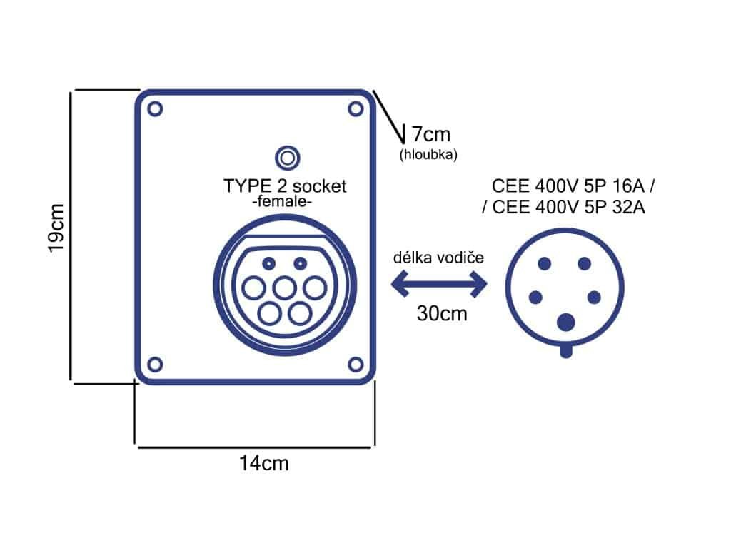
22kw portable wallbox type 2 socket with cee plug
Miller 14 pin connector wiring diagram. For miller and hobart machines with 14 pin plugs and 1k potentiometers. Kenne bell boost a pump wiring diagram. With a meter on ac voltage check between pins a b. None in the owners manuel or on millers website that i can find 01 13 2012 1145 am 8. I see the point made about removing the c clip from the ...
Weldingweb - welding community for pros and enthusiasts

Inserting a pin in a 8 and 14 pin connector
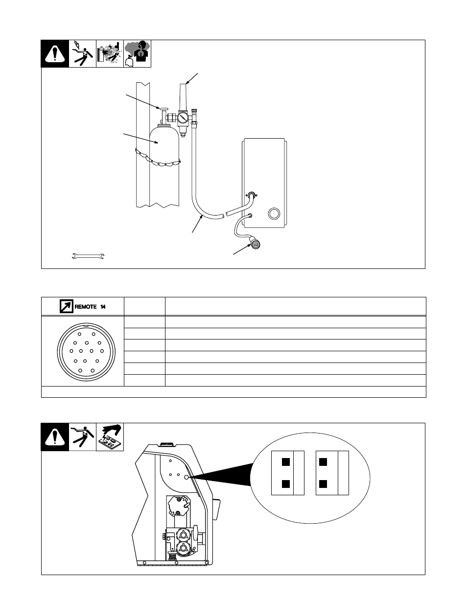
4. connecting shielding gas and 14-pin plug, 5. 14-pin plug ...
Spoolmatic 30a gun pinout diagram? illustration? - miller ...
Weldingweb - welding community for pros and enthusiasts

Ssc remote foot pedal for miller tig welders - 14pin plug ...
Trailblazer remote wiring? - miller welding discussion forums
Miller rccs-14 (043688) user manual | manualzz
Weldingweb - welding community for pros and enthusiasts
The ssc controls company
14 pin help for tig switch and solenoid wiring - miller ...

Miller 300507 6 pin to 14 pin remote control adapter cord ...

Ssc controls 14 pin male plug for miller welders p/n 141162 or 136961 (3106a-20-27p and 3057-12-6)

Big blue 500x eco pro - miller

Miller rj45 to 14-pin remote control adapter cord 300688

Practical machinist - largest manufacturing technology forum ...
0 Response to "37 miller 14 pin connector wiring diagram"
Post a Comment