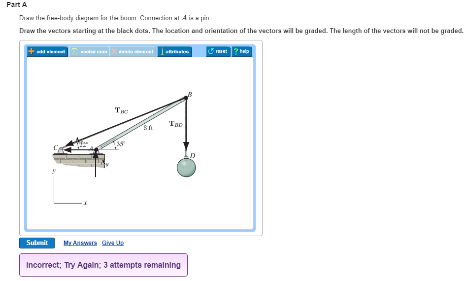
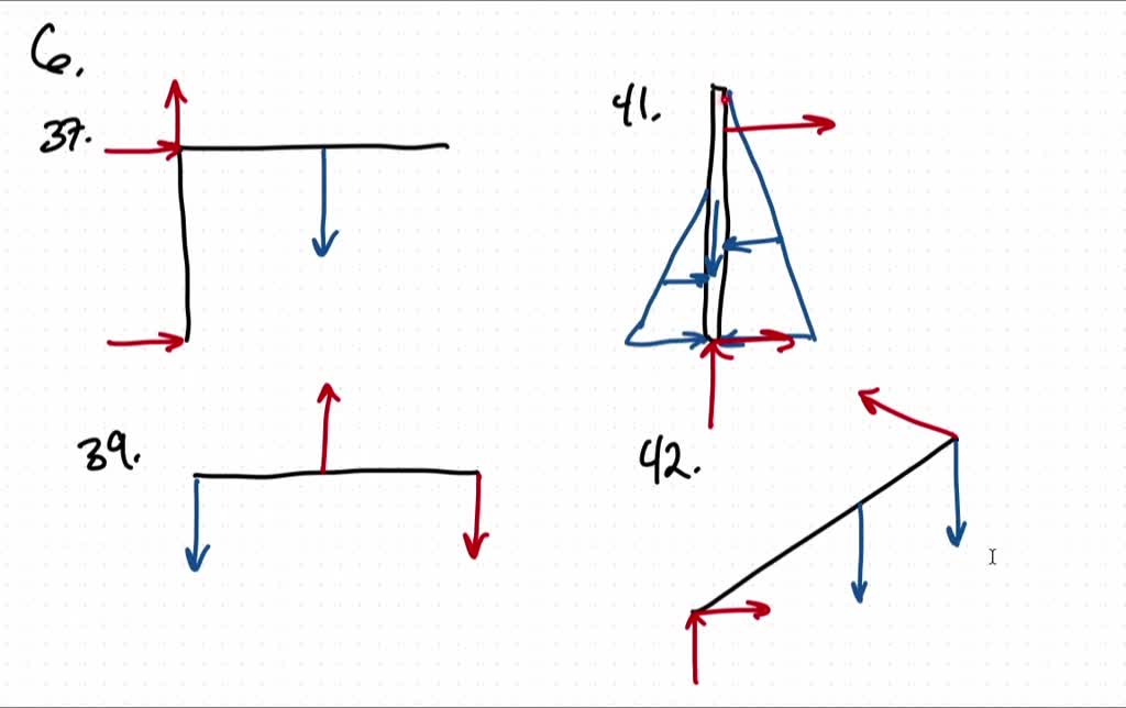
37 draw the free-body diagram for the boom. connection at a is a pin.
Draw the free-body diagram needed to determine the tension in AC and BC. SOLUTION Free-Body Diagram of Point C: W = (1600 kg)(9.81 m/s 2 ) W = 15.6960(103 ) N W =15.696 kN
FREE-BODY DIAGRAMS (Section 5.2) 2. Show all the external forces and couple moments. These typically include: a) applied loads, b) support reactions, and, c) the weight of the body. Idealized model Free-body diagram (FBD) 1. Draw an outlined shape. Imagine the body to be isolated or cut “free” from its constraints and draw its outlined shape.
• A free body diagram of the complete frame is used to determine the external forces acting on the frame. • Internal forces are determined by dismembering the frame and creating free -body diagrams for each component. • Forces between connected components are equal, have the same line of action, and opposite sense.

Draw the free-body diagram for the boom. connection at a is a pin.
pin in joint B. See the diagram in the lower right of Figure 3-2. Step 2: The set of free-body diagrams is shown in Figure 3-3. Step 3: Now consider the free-body diagrams of all of the members in Figure 3-3. We have already discussed member 1, recog-nizing it as a two-force member in tension carrying forces RA and RC equal to 48.07 kN.
Engineering Mechanics - Statics Chapter 5 Problem 5-1 Draw the free-body diagram of the sphere of weight W resting between the smooth inclined planes. Explain the significance of each force on the diagram. Given: W = 10 lb θ 1 = 105 deg θ 2 = 45 deg Solution: NA, NB force of plane on sphere. W force of gravity on sphere.
Free-Body Diagram.The x, y, z axes are established at B and the free-body diagram of segment AB is shown in Fig. 1-8b.The resultant force and moment components at the section are assumed to act in the positive coordinate directions and to pass through the centroid of the cross-sectional area at B. The weight of each segment of pipe is
Draw the free-body diagram for the boom. connection at a is a pin..
Screen recordings of Statics Power software from Actus Potentiahttp://www.actuspotentia.com/Statics.shtml
Free-Body Diagram: 2 1 2 (40 kg)(9.81 m/s ) 392.40 N (300 mm)sin (80 mm)cos (430 mm)cos (300 mm)sin (930 mm)cos Wmg a a b αα αα α == = =− =− = From free-body diagram of hand truck, Dimensions in mm MPbWaWa B 0: ( ) ( ) ( ) 0 21 (1) FPWB y 0: 2 2 0 (2) For α=°35 1 2 300sin35 80cos35 106.541 mm 430cos35 300sin35 180.162 mm 930cos35 761 ...
Common Types of Trusses Bridge Trusses In particular, the Pratt, Howe,and Warren trusses are normally used for spans up to 61 m in length. The most common form is the Warren truss with verticals. For larger spans, a truss with a polygonal upper cord, such as the Parker truss, is used for some savings in material.
1. If the support reactions are not given, draw a FBD of the entire truss and determine all the support reactions using the equations of equilibrium. 2. Draw the free-body diagram of a joint with one or two unknowns. Assume that all unknown member forces . act in tension (pulling the pin) unless you can determine
4.2 Free Body Diagrams The free body diagram is a depiction of an object or a body along with allthe external forces acting on it. • Choose and draw the body (with dimensions). Carefully define its boundaries. • Imagine the body in its current state and how it interacts with its surroundings. • Draw ALL the external forces acting on the ...
No part of this Manual may be displayed, reproduced or distributed in any form or by any means, without the prior written permission of the publisher, or used beyond the limited distribution to
Free Body Diagrams. A free body diagram is a tool used to solve engineering mechanics problems. As the name suggests, the purpose of the diagram is to "free" the body from all other objects and surfaces around it so that it can be studied in isolation. We will also draw in any forces or moments acting on the body, including those forces and ...
Drawing Free-Body Diagrams. Free-body diagrams are diagrams used to show the relative magnitude and direction of all forces acting upon an object in a given situation. A free-body diagram is a special example of the vector diagrams that were discussed in an earlier unit. These diagrams will be used throughout our study of physics.
The above diagrams, which show the complete system of applied and reactive forces acting on a body, are called free body diagrams. The whole system of applied and reactive forces acting on a body must be in a state of equilibrium. Free-body diagrams are, consequently ,often called equilibrium diagrams. Drawing equilibrium diagrams and finding
Free-Body Diagram 4 - 4 The first step in the static equilibrium analysis of a rigid body is identification of all forces acting on the body with a free body diagram. • Select the body to be analyzed and detach it from the ground and all other bodies and/or supports. • Include the dimensions, which will be needed
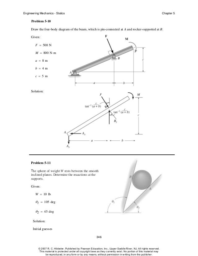
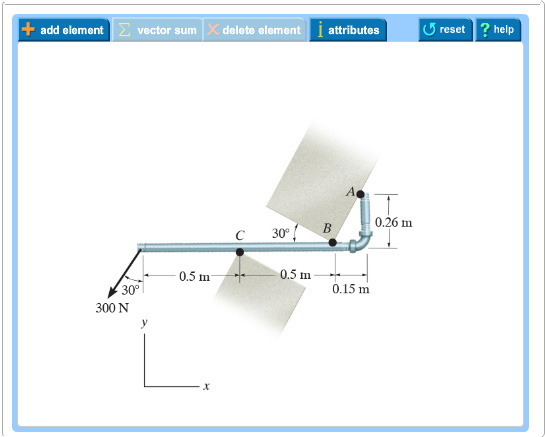
Draw the free-body . diagrams for each pipe and . both pipes together. 5-10 Free-Body Diagrams. Solution For idealized models, Free-Body Diagram of pipe A. 5-11 p.216, 5-9. Draw the free-body diagram of the beam, which is pin- connected at A and rocker-supported at . B. 5-12
A short video to show how to form an imaginary cut and draw a free body diagram of a simply supported beam with a point load.Related videos:Reactions of a Si...
Aula equilibrio | pdf
Knowing that 8 kNAF and 16 kN,BF determine the magnitudes of the other two forces. SOLUTION Free-Body Diagram of Connection 3 3 0: 0 5 5 x B C AF F F F With 8 kN, 16 kNA BF F 4 4 16 kN 8 kN 5 5 CF 6.40 kNCF 3 3 0: 0 5 5 y D B AF F F F With AF and BF as above: 3 3 16 kN 8 kN 5 5 DF 4.80 kNDF 154 155.

Solved part a draw the free-body diagram for the boom ...
37 Free Body Diagrams Wednesday, October 3, 2012 New Support Conditions Pin Connection ! Another way Here is a pin support 38 Free Body Diagrams Wednesday, October 3, 2012 New Support Conditions Pin Connection ! On a pin, we know that there is an x and a y component of the reaction but without other
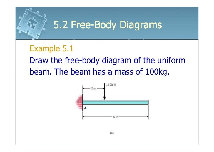
6161103 5.2 free body diagrams
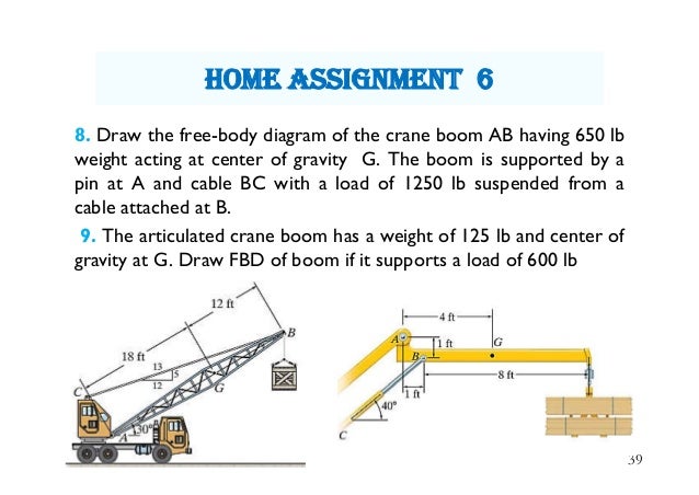
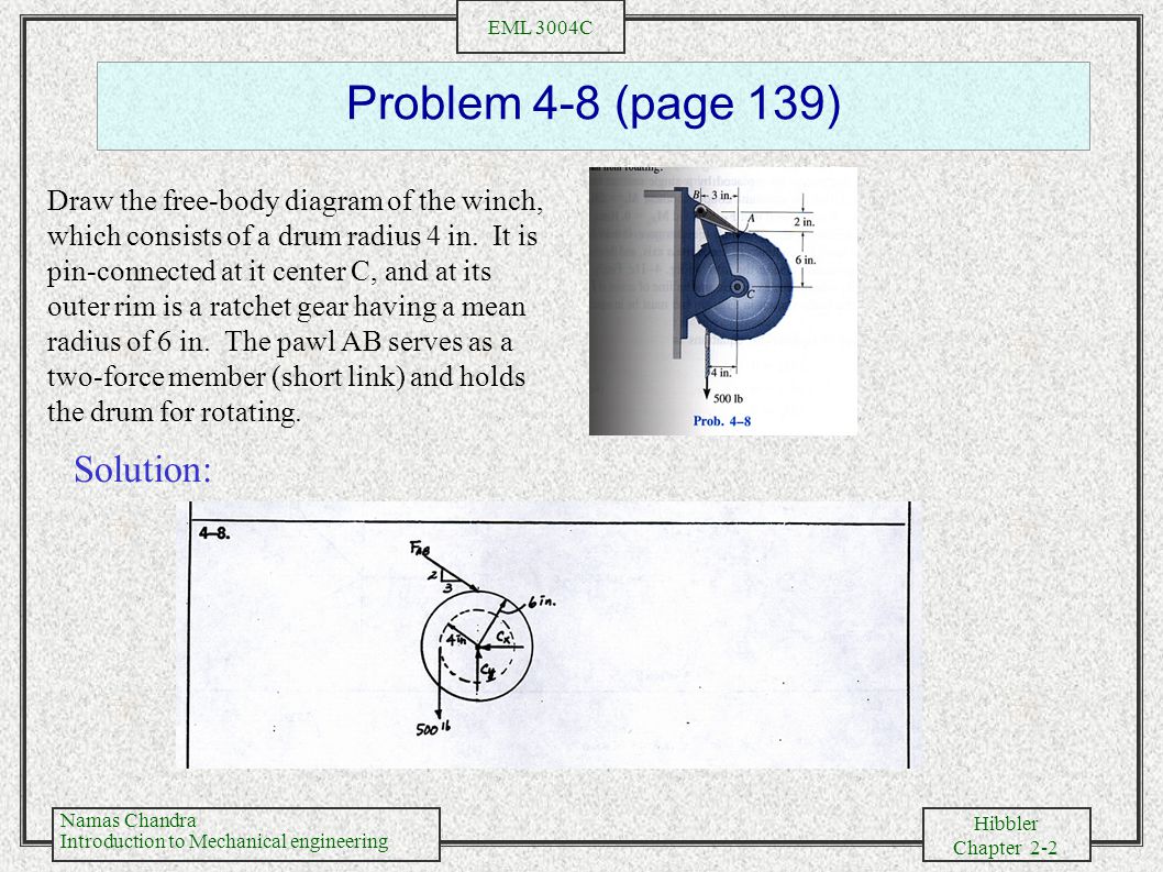
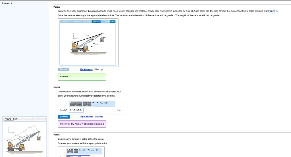
8. Draw the free-body diagram of the crane boom AB having 650 lb weight acting at center of gravity G. The boom is supported by a pin at A and cable BC with a load of 1250 lb suspended from a cable attached at B. 9.
Untitled
Figure 5.32 (a) The free-body diagram for isolated object A. (b) The free-body diagram for isolated object B. Comparing the two drawings, we see that friction acts in the opposite direction in the two figures. Because object A experiences a force that tends to pull it to the right, friction must act to the left. Because object B experiences a component of its weight that pulls it to the left ...

Draw the free body diagram for the boom connection at a is a ...
39 draw the free-body diagram for the boom. connection at a is a pin. Written By Christine J. Bell. Tuesday, November 30, 2021 Add Comment Edit. In a free-body diagram we draw the system somewh at real is tically and replace ... To get a feeling for the for ce at a pin connection consider the physical ...
Solved draw the free-body diagram for the boom. connection ...
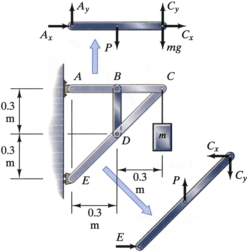
15. The free-body diagrams for links DC, BC, AB, AD, and BD are: B A 1500 2 = 2121 2121 B C 1500 1500 D B 3000 3000 A D 1500 1500 C D 1500 2 = 2121 2121 16. We can now draw a free-body diagram of pin B: B 2121 N 3000 N 1500 N 1500 N 45˚ 17. Checking for static equilibrium at pin B gives: x!F = 2121 cos 45˚ - 1500 = 0 y!F = 1500 + 2121 sin 45 ...
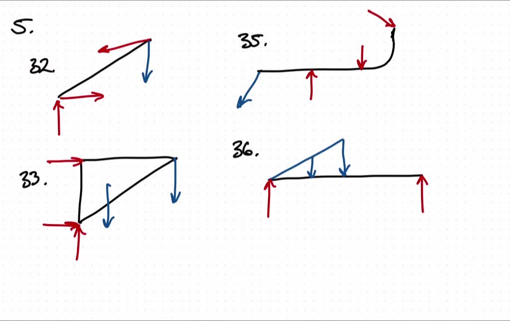
Module 6 updated
5—6. the free-body diagram af the crane boom AB which has a weight of 650 1b and center of gravity at G. The boom is supported by a pin at A and cable BC. The load of 1250 1b is suspended from a cable attached at B. Explain Lhc significance of each force acting on the diagram. (See Dr. Ahmed A. Abu-foul T.A: Eng. Waseem (Younis 30 sithBo COS So
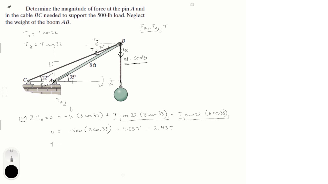
Determine the magnitude of force at the pin a and cable
Nov 11, 2013 · Engineering Mechanics - Statics Chapter 5 Problem 5-10 Draw the free-body diagram of the beam, which is pin-connected at A and rocker-supported at B. Given: F = 500 N M = 800 N⋅ m a = 8m b = 4m c = 5m Solution: Problem 5-11 The sphere of weight W rests between the smooth inclined planes. Determine the reaactions at the supports.
Solved] body incomplete fbd 1. bell crank supporting mass m ...
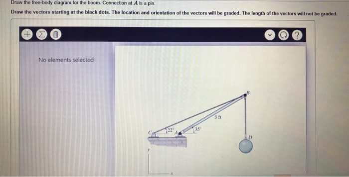
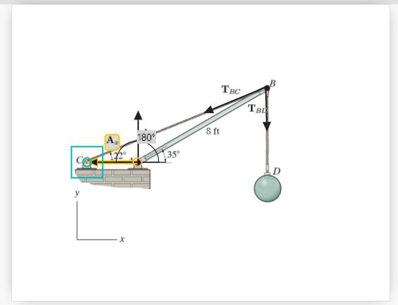
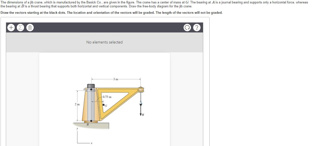
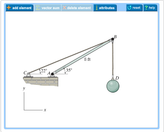
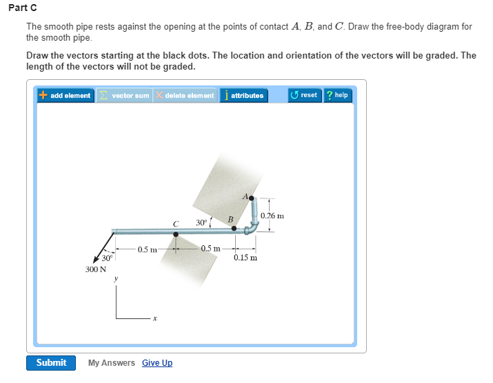
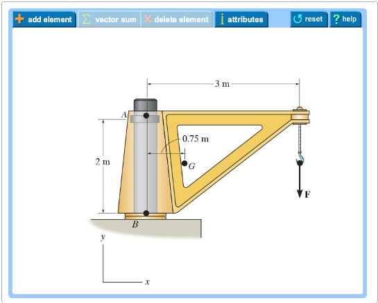
Draw the free-body diagram for the boom. Connection at A is a pin. Draw the vectors starting at the black dots. The location and orientation of the vectors will be graded. The length of the vectors will not be graded. The dimensions of a jib crane, which is manufactured by the Basick Co., are given in the figure.
Solved draw the free-body diagram for the boom. connection ...
Examples of drawing free-body diagrams. To better understand how to draw free-body diagrams using the 3 steps, let's go through several examples. Example 1. A box is pushed up an incline with friction which makes an angle of 20 ° with the horizontal. Let's draw the free-body diagram of the box. The first step is to sketch what is happening:
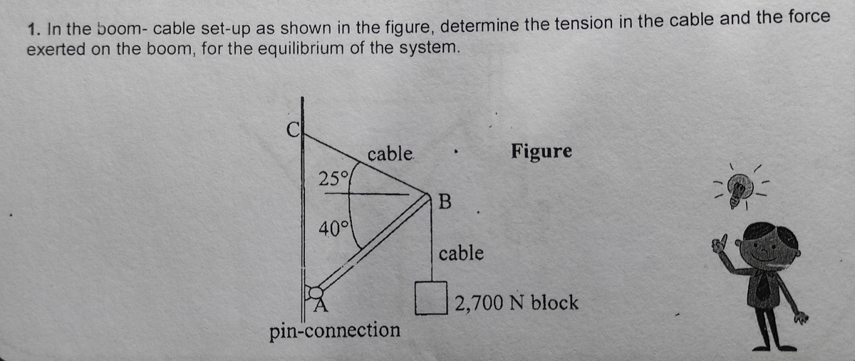
Answered: the boom- cable set-up as shown in the… | bartleby
A 10-ft boom is acted upon by the 840-1b force shown. Determme the tension in cach cable and the leaclion at the ball-and-socket joint at A. SOLUTION We have five unknowns and six equations of equilibrium. but equilibnum is maintained (EM Free -Body Diagram: + 7j+ 6k) BE 11 (_6i + 6i + — 6k) + (—840) O 11001b 11001b _ë_6î
Solved part a draw the free-body diagram for the boom ...
Question: Draw the free-body diagram for the boom. Connection at A is a pin. Draw the vectors starting at the black dots. The location and orientation of the vectors will be graded. The length of the vectors will not be graded. The dimensions of a jib crane, which is manufactured by the Basick Co., are given in the figure.
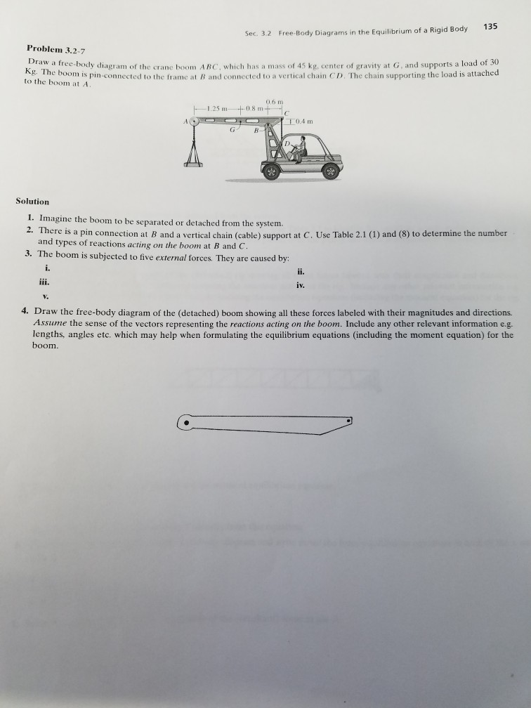
Solved draw a free-body diagram of the boom abc, which has ...
Draw the free body diagram for the boom connection at a is a ...
Draw the free body diagram for the boom connection at a is a ...
Solved:equilibrium of a rigid body | engineering mechanics ...
Solved draw the free-body diagram for the boom. connection ...
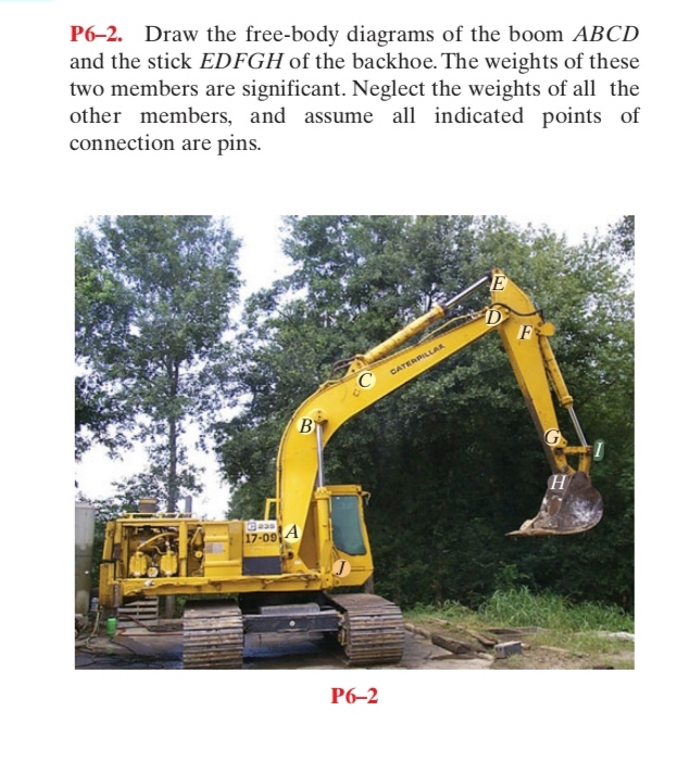
Answered: p6–2. draw the free-body diagrams of… | bartleby
Solved:equilibrium of a rigid body | engineering mechanics ...
Draw the free body diagram for the following problems a the boom in prob 5 32 b the jib crane in p 2
Part a draw the free-body diagram for the boom. | chegg.com

Draw the free body diagram for the boom connection at a is a ...
Solved part a draw the free-body diagram for the boom ...
Solved draw the free-body diagram of the crane boom ab which ...
Solved:equilibrium of a rigid body | engineering mechanics ...

Draw the free body diagram for the boom connection at a is a ...
Solved:draw the free-body diagram for the following problems ...
Solved:draw the free-body diagram for the following problems ...
Part a draw the free-body diagram for the boom. | chegg.com
Introduction | springerlink
Part a draw the free-body diagram for the boom. | chegg.com
Draw the free body diagram for the following problems a the boom in prob 5 37 b the bulk head in pro
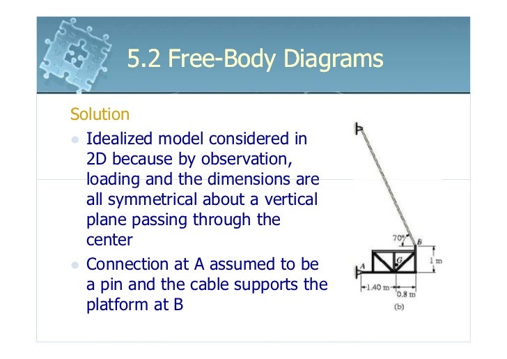
6161103 5.2 free body diagrams
Draw the free body diagram for the boom connection at a is a ...
![Solved] Draw the free-body diagram of the crane boom AB which ...](https://www.solutioninn.com/images3/50-E-C-S(1795).PNG)
Solved] draw the free-body diagram of the crane boom ab which ...
Solved:equilibrium of a rigid body | engineering mechanics ...
0 Response to "37 draw the free-body diagram for the boom. connection at a is a pin."
Post a Comment