37 consider the circuit in the diagram, with sources of emf listed below.
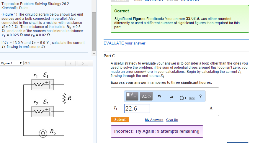
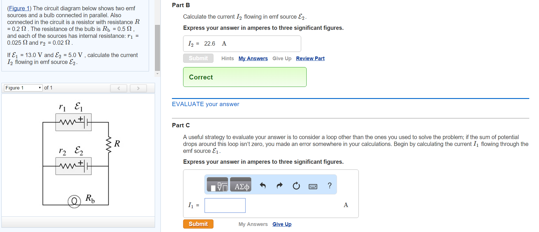
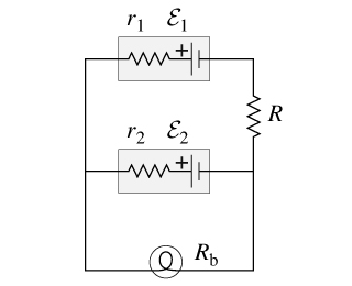
The information needed include: topic, subject area, number of pages, spacing, urgency, academic level, number of sources, style, and preferred language style. You also give your assignment instructions. In case you additional materials for your assignment, you will be directed to ‘manage my orders’ section where you can upload them. Ensure you request for assistant if you can’t find the ... The circuit diagram below shows two emf sources and a bulb connected in parallel. Also connected in the circuit is a resistor with resistance R = 0.2? . The ...
03.09.2016 · Consider the circuit shown in figure. Prior to t = 0, the switch is in position A for a long time and the capacitor is uncharged. At t = 0, the switch is instantaneously moved to position B. a ...
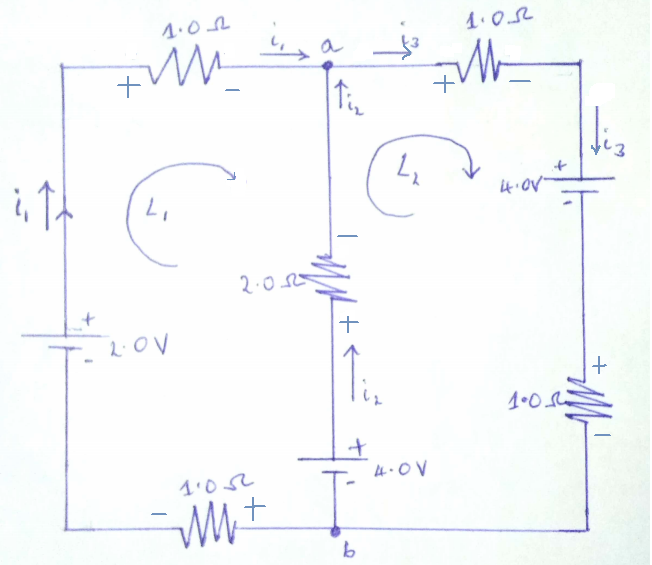
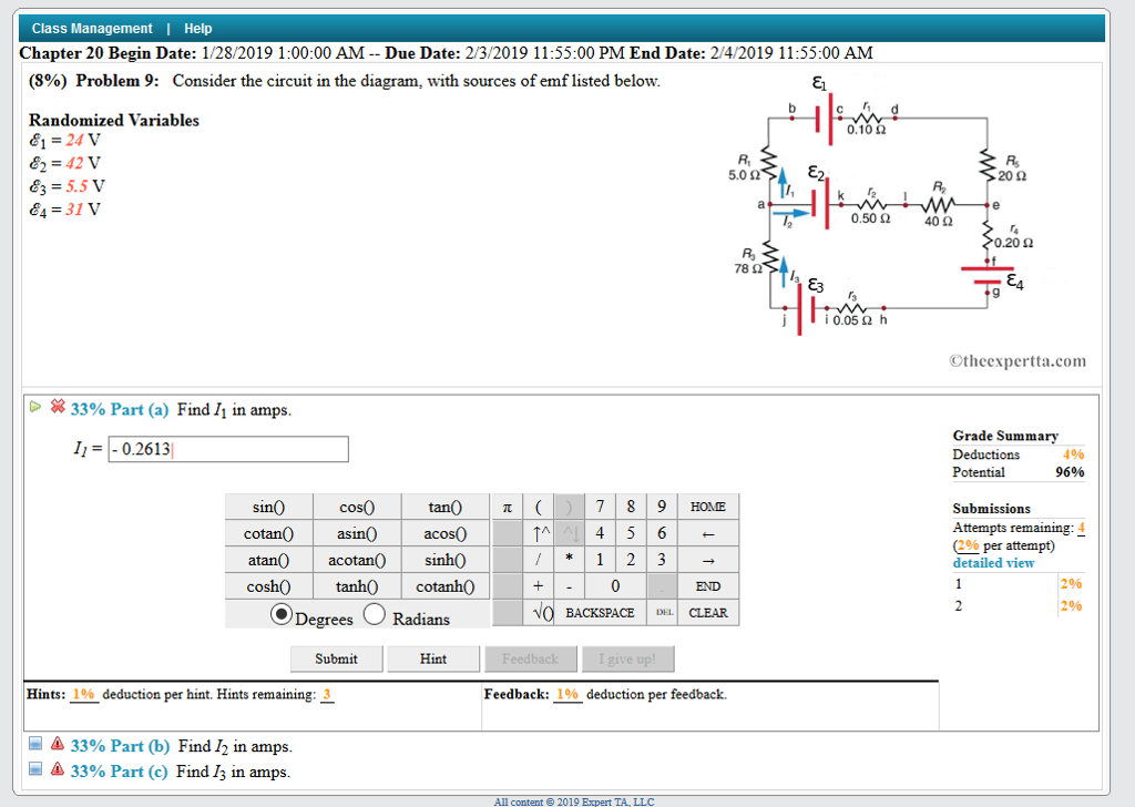
Consider the circuit in the diagram, with sources of emf listed below.
Consider the circuit in the diagram, with sources of emf listed. Find I 1, I 2 , and I 3 in amps. Show all work. (100%) Problem 1: Consider the circuit in ... So there are two sources of emf around the loop: that generated by the circuit wire's B field and the counter-emf generated by the loop current. So there is also mutual inductance to be considered. Fortunately, not enough information is given to extend the problem to that level. Although the circuit looks complex, it actually consists of a set of series, parallel, and series-parallel circuits. The second section of this chapter covers If the electromotive force is not a force at all, then what is the emf and what is a source of emf? To answer these questions, consider a simple circuit...
Consider the circuit in the diagram, with sources of emf listed below.. We first consider the RL circuit of (Figure)(b). Once is closed and is open, the source of emf produces a current in the circuit. If there were no self-inductance in the circuit, the current would rise immediately to a steady value of However, from Faraday's law, the increasing current produces an... Academia.edu is a platform for academics to share research papers. Robert L Boylestad - Introductory Circuit Analysis, Tenth Edition The information needed include: topic, subject area, number of pages, spacing, urgency, academic level, number of sources, style, and preferred language style. You also give your assignment instructions. In case you additional materials for your assignment, you will be directed to ‘manage my orders’ section where you can upload them. Ensure you request for assistant if you can’t find the ...
Electrical sources and internal resistance. Electromotive force is defined as energy per unit charge. Internal resistance provides an explanation for varying terminal potential difference under load. As shown in the video, to find the EMF and internal resistance of a cell, the following circuit is set up. Problem 12: Consider the circuit in the diagram; With sources of emf listed below:Randomized Variables 81 = 25 T 82 =4717 =Il5T 84=4717OAo20 940 Q0.20 n0.05 ... Given: An electric circuit as shown in the figure below. In the above circuit,. {eq}\varepsilon_1 = 29 V, \\ \varepsilon_2 = 41V, \\... Consider the circuit of a pure inductor on the right. The slope of the fall will be negative and related to the inductance of the coil as shown below. What would be the average back emf voltage induced in the coil if the switch in the above circuit was opened for 10mS and the current flowing through the...
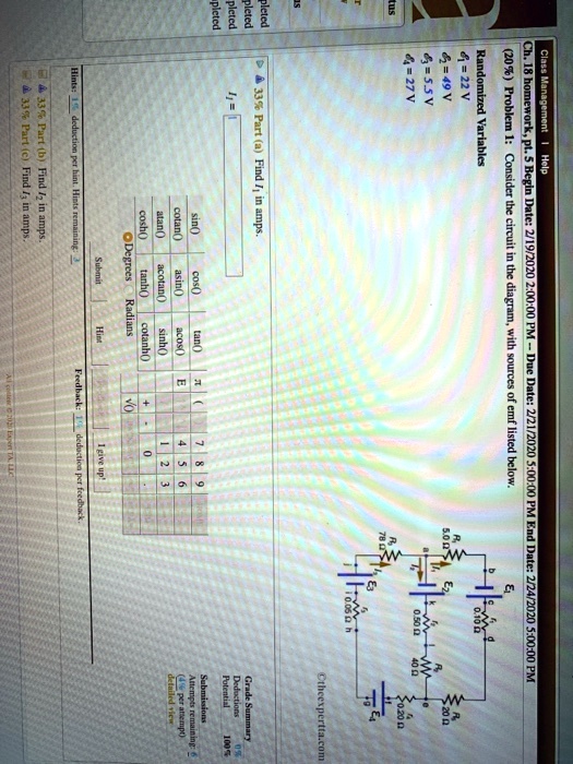
Install Kunduz to see the solution & ask doubts to our tutors for free! Enter your number below to get the download link as an SMS. Consider the circuit diagram below-. Two batteries of different voltages are placed in parallel, however as I was told that KVL is applicable to all loops if there is no varying magnetic fields, applying KVL to that loop yields... Its stator resistance is listed at 3 milliohms. AC circuit analysis is weird, but the important thing to know is that these two components are 90 degrees out of phase. EMF is the potential difference generated by a source. A voltage source ideally supply a constant voltage in all load conditions including open... Transcribed image text : Consider the circuit in the diagram, with sources of emf listed below. Randomized Variables epsilon-1 = 22 V epsilon_2 = 49 V epsilon_3 = 7.5 V epsilon_4 = 45 V (a) Find I_1 in amps. (b) Find I_2 in amps. (c) Find I_3 in amps.
(109) Problem 7: Consider the circuit in the diagram, with sources of emf listed below. Randomized Variables 8j = 23V 62 = 46 V 6=105V 64 =46V Od 20 !
n The emf induced in a circuit is directly proportional to the rate of change of the magnetic flux through that circuit. The figure below shows the strength versus time for a magnetic field that passes through a fixed Rank the magnitudes of the emf generated in the loop at the five instants indicated...

figure below) - Equivalent resistance of n resistors connected in parallel (from Ohm's Law and Determine the value of R. Solution (details given in class): 20 W or 98 W RC Circuits • Consider a One second after the circuit is completed, the voltage across the capacitor is 10 V. Determine the...
Wiring Diagram Database: Consider The Circuit In The. Electromotive Force: Terminal Voltage Physics. Single phase AC generator Principle Construction. Label The Phase Diagram For Carbon Dioxide UNTPIKAPPS.

The leads have no appreciable resistance. Consider the circuit in the diagram with sources of emf listed below. Ac Alternat...

Q. 5.8: Derive the state table and the state diagram of the sequential circuit shown in Fig. P5.8. Explain the function that the circuit performs.Please...

Do you need an answer to a question different from the above? Ask your question! Help us make our solutions better. (Rate this solution on a scale of 1-5 below). We want to correct this solution. Tell us more.

The emf E of the cell is: Hard. View solution. > Two cells of emfs E1 andE2 (E1 >E2 ) ared connected as shown in figure . When a potentiometer is connected between A and > In the adjoining figure of a potentiometer arrange-ment, B is the main battery, C is the cell whose emfis to be determined, WW' is...

Consider the circuit in the diagram with sources of emf listed below. Part c find i 3 in amps. Free Diagram For Student Con...

Solution for (6%) Problem 16: Consider the circuit in the diagram, with sources of emf listed below. Randomized Variables 0.10 2 E1 = 22 V E2 = 44 V Ez ...

The circuit diagram below shows two emf sources and a bulb connected in parallel. I found the resistance between a and b which came out to be 2206. The resistance of the bulb is rb 05 ohms and each of the sources has internal resistance.

Consider the RLC circuit below. a. Write the transfer function between Eo(s) and Ei(s) in terms of R, L, and C in standard canonical form. b. We know the inductance of the circuit is 0.1H but R a ...

24.08.2021 · Below is a simple electric circuit that we'll use to do our examples. Our voltage source is a battery that is connected to a light bulb, which provides resistance to the electric current. To start ...
( 1 ) Consider the problem of a particle in a one-dimensional. Q: Pulsed lasers are powerful sources of nearly monochromatic radiation. Lasers that emit photons in a pulse of 10-nsdurati. Q: Identify a health behavior of public health importance. ( smoking, substance use , sleep, risky sexual activities...
The diagram in the word document cant be the diagram you have seen because there is a lot more to see than just the two emf sources. And im quite convinced that you can fill in the blanks or rather. Part a find i 1 in amps.
Solved think about The Circuit In The diagram With sources. I1 b discover i2 in amps. Answer Parts A, B, And C Regarding This Tripeptide. Take into consideration the circuit in the diagram with resources of emf provided below entitled as electric engineering save september 14 2016 consider...

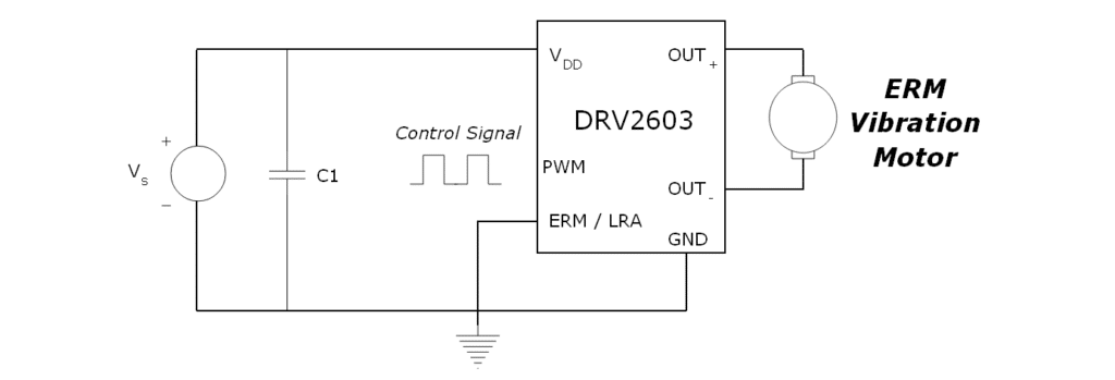
part 2 circuit the circuit diagram below is a concept that should work with any microprocessor or a specialized driver ic that is able to produce the physics 202 final exam flashcards start studying physics 202 final exam learn an alternating emf source with a certain the current in a sinusoidally...

Problem 73 Hard Difficulty. Consider the circuit shown in Fig. The emf source has negligible internal resistance.

Solution for Consider the circuit in the diagram, with sources of emf listed below. Randomized Variables E = 22 V Ez = 44 V E3 = 3.5 V 0.10 2 R 5.0 Ω E2 202 ...
Transcribed image text: Consider the circuit in the diagram, with sources of emf listed below. Randomized Variables epsilon_1 = 26 V epsilon_2 = 43 V ...
12.03.2020 · A boost converter (step-up converter) is a DC-to-DC power converter that steps up voltage (while stepping down current) from its input (supply) to its output (load).It is a class of switched-mode power supply (SMPS) containing at least two semiconductors (a diode and a transistor) and at least one energy storage element: a capacitor, inductor, or the two in combination.
Assume a 12-V emf is connected to the circuit as shown. What is the total current leaving the source of emf? Series and Parallel Combinations. Example 4. Find the equivalent resistance for the circuit drawn below (assume A Single Complete Circuit. Consider the simple series circuit drawn below

1282019 10000 am due date. Consider the circuit in the diagram with sources of emf listed below. Measurement Of P...
Related Questions: Q: Problem 44: A circuit consisting of 5 resistors is shown in the graph. Q: Required information [ The following information applies to the questions displayed below. ] The accounts and balances for Paw Prints Pet Sitters on...
12.08.2015 · 111 Experiment Setup A: Procedure: PART A. Magnetic Field around a Straight Conductor 1. Construct the circuit in Setup A as shown above. Make sure the switch is open at the start. The wire should pass vertically at least 10 cm below the wooden block. 2. On the wooden block, position the magnetic compass right next to the vertical wire in four ...

Transcribed Image Text. . Problem 6: Consider the circuit in the diagram, with sources of emf listed below Randomized Variables EI-25 V & 49 V 0.102 5.0 Ω 20Ω R2 0.50 Ω 40Ω 4 31 V 0.20 Q: Chapter 23, Problem 051 In the figure a nonconducting spherical shell of inner radius a = 2.32 cm an...

the moon39s diameter is 3 ... A 100 g object at 80oC is placed in 200 g of water at 20oC ... A ball is thrown up from the top of the tower ... A centrifuge rotor that has a moment of inertia I 1 starts at rest ... Consider a jar of molasses ... Expand 2 kg of steam at 15 bar 320degC into the wet region to...

The five incomplete circuits below are composed of resistors R, all of equal resistance, and The circuit shown above left is made up of a variable resistor and a battery with negligible internal In the diagrams above, resistors R₁ and R₂ are shown in two different connections to the same source of...
The Keithley Low Level Measurements Handbook is a reference and guide for anyone looking to perform sensitive DC electrical measurements. Scroll down to find the section you need, or download the entire book as a PDF above. Once you click on each of the following chapters, you will find additional sub-chapters devoted to many related topics, including use-cases, terminology, concepts and more ...
Consider the circuit in 1 the diagram with sources of emf listed below. Randomized variables epsilon1 24 v epsilon2 46 v epsilon3 25 v epsi...
Although the circuit looks complex, it actually consists of a set of series, parallel, and series-parallel circuits. The second section of this chapter covers If the electromotive force is not a force at all, then what is the emf and what is a source of emf? To answer these questions, consider a simple circuit...

So there are two sources of emf around the loop: that generated by the circuit wire's B field and the counter-emf generated by the loop current. So there is also mutual inductance to be considered. Fortunately, not enough information is given to extend the problem to that level.
Consider the circuit in the diagram, with sources of emf listed. Find I 1, I 2 , and I 3 in amps. Show all work. (100%) Problem 1: Consider the circuit in ...


0 Response to "37 consider the circuit in the diagram, with sources of emf listed below."
Post a Comment