41 wastewater treatment plant process flow diagram
Hi there, ​ I have a test for a plant technician wastewater position next Wednesday. This is for the City of Toronto. I am currently studying off a study guide I purchased from OMWA (Ontario Municipal water Association) for operator in training manual and mathematics for water and wastewater operations. I have written this test before and noticed that the test I previously wrote has a lot of content not in my study guide. ​ Things that were asked in the previous test... Keywords: compact plants, wastewater treatment, nitrogen and phosphorus removal, waste liquid temperature, modern technology. Taking into account the abovementioned facts, a process flow diagram for domestic wastewater treatment is given below, which can be used in CP design (Figure...
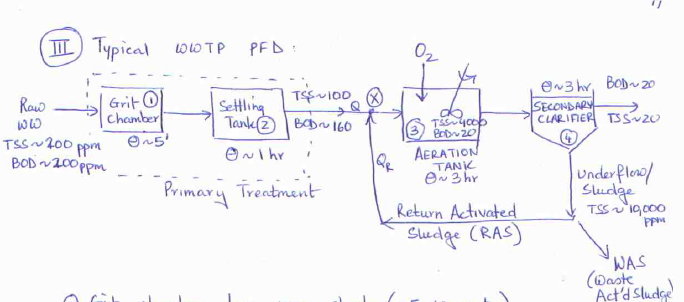
Figure 1-1 Process flow diagram of a typical wastewater treatment plant with upstream denitrification. The actual feed flow rate is regarded as a measurable disturbance variable in the higher-level multivariable controller. (2) Aeration tank The ammonium concentration (NH4) and nitrate...

Wastewater treatment plant process flow diagram
Figure 5.6 . Process flow diagram of wastewater treatment plant including a mass balance (gpm) based on 24 average during continuous operation. The flow then enters a reverse osmosis plant containing three parallel streams designed at 50% flow enabling continuous operation. The soap manufacturing process flow diagram is shown in figure 1. Receiving Storage Transfer Fatty Acid Caustic Soda Sodium Chloride (Salt) Sodium The degree of treatment can be determined by comparing the influent wastewater characteristics to the required effluent wastewater characteristics. The municipality has 27 wastewater treatment plants which discharge their final effluent into the nearest river in the respective areas. The receiving rivers are exposed to contamination. To avoid or reduce such contamination, the final treated effluent must have acceptable levels of compliance to...
Wastewater treatment plant process flow diagram. During the treatment facility design process, possible impacts of design flows and loadings on each upstream and downstream unit process should be Use Table 2 for flow calculations. Table 3 should be used to determine the design loadings for a new or upgraded wastewater treatment plant. The design of wastewater treatment plants is usually based on the need to reduce organic and suspended solids loads to limit pollution of the The short-term variations in wastewater flows observed at municipal wastewater treatment plants follow a diurnal pattern. Flow is typically low... Contains sequence of unit operations of WTP, Preliminary, Primary, Secondary and Tertiary Treatments. MBBR wastewater treatment process design spreadsheets are included in all of the wastewater treatment spreadsheet bundles described above. A flow diagram for a typical single stage trickling filter wastewater treatment plant is shown in the diagram below.
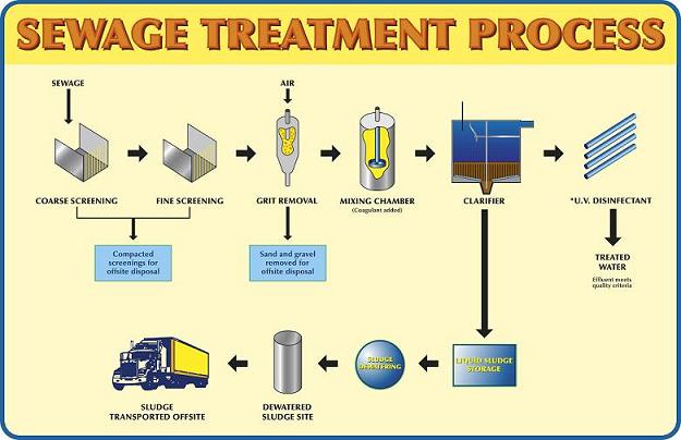
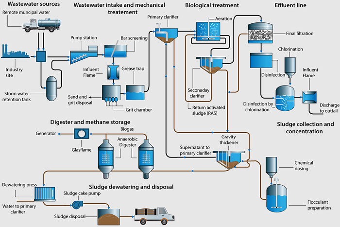
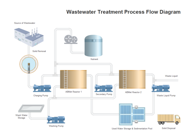
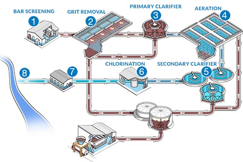
• ETP (Effluent Treatment Plant) is a process design for treating the industrial waste water for its reuse or safe disposal to the environment. • Monetary considerations for construction, operation & maintenance. • Area dimension depends on: Ø Quality of wastewater to be treated, Ø Flow rate Ø... This diagram shows the physical layout of a wastewater treatment plant. Wastewater is any water that requires cleaning after it is used. A process flow diagram (PFD) is a diagram commonly used in chemical and process engineering to indicate the general flow of plant processes and equipment. Sewage treatment, or domestic wastewater treatment, is the process of removing contaminants from wastewater and household sewage, both runoff (effluents) and domestic. It includes physical, chemical and biological processes to remove physical, chemical and biological contaminants. Also, the type of treatment processes employed in the plant and the contaminant removal efficiency control the amount of GHG emission in a given WWTP. Figure 2-1 presents the flow diagram of different wastewater treatment systems and the potential sources of GHG emission.
These process flow diagrams allow discharging industrial wastewater into the city sewage network and recycling water supply of textile facilities. [Show full abstract] a treatment plant are quite comparable with the costs which the operators of municipal wastewater treatment plants must meet... DWU Raw Water Source and Treatment Facilities. Flow Diagram for Hydrostatic & Bacteriological Testing Process. DWU Wastewater Treatment Plants (WTP). Typical Pipe Trench. New Wastewater Main Parallel to Existing Water Main. 50 wastewater treatment facilities. 51. Plant Location 52. Quality Of Effluent 53. The process of selection of wastewater treatment alternatives for detailed evaluation should be discussed. Flow diagram of treatment facilities including all recycle flows. f. Emergency Operation. Drinking water treatment plant process animation. Raw water from a surface water lake or reservoir is drawn into the plant through i... Biological And Chemical Wastewater Treatment Processes Intechopen. Sunman textile mills ltd. Water treatment plant process flow diagram .
Samantha Schuster This Is A Lengthy But Informative Article That Talks About All The Steps Water Water Treatment Plant Water Treatment Water Treatment System
Ana Sayfa İncelemeler Wastewater Treatment Plant Process Flow Chart. Wastewater Treatment Plant Process Flowchart. This image throws light upon the four processes of wastewater treatment.
Sewage Treatment Process Water Treatment Waste Water Treatment Water Treatment Process Plant Design
[Meena Development LTD.](https://www.littlepeng.com/meena-development-ltd), is a premier provider of [Piping Design Solutions](https://www.littlepeng.com/single-post/2020/04/25/piping-design-services-company-canada) and [Engineering Services](https://www.littlepeng.com/engineering-services-toronto-on). Our fields of specialty are [Piping Stress Analysis](https://www.littlepeng.com/single-post/affordable-pipe-stress-analysis-services-outsourcing-company-across-canada), [Plant Layout](https://www....
Answer The Following Question Related To The Process Chegg Com
Table of Contents Wastewater Treatment Blower Selection Activated Sludge Process, Upgrade with IFAS The blower diagram usually consists of two curves the CFM vs. the SP curve showing the...

Petropath Fluids India Pvt Ltd
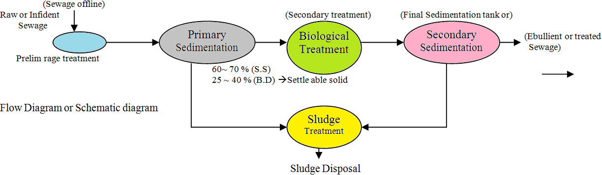
The process flow diagram of a typical wastewater treatment plant is furnished in Table. The main purpose of the primary treatment is to produce a generally homogeneous liquid capable of being treated biologically and a sludge that can be separately treated or processed.

K Chemical Corporation K Plant Common Wastewater Treatment Facility
Wastewater Treatment Process Flow Diagram. To make wastewater able for drinking and for other household chore purposes, wastewater treatment plants use a combination of physical and biological processes for purification known as Wastewater treatment or Sewage treatment, these treatment...
A Guide To Measurement In Wastewater Treatment Pumps Systems
Process Flow Diagram For Aspropyrgos Water Treatment Plant. Pin By Industrial Wastewater On Electro Oxidaiton. Electrical contractors know that aluminum Process Flow Diagram Wastewater Treatment Plant is usually a concealed Hazard in several homes.

Konya Wastewater Treatment Plant Flow Diagram 2 3 Youtube
The wastewater treatment lectures are designed to provide insight into the processes and techniques that are applied in the wastewater treatment eld, where the focus is laid on the basic principles, local conditions, basic circumstances and performance processes. Their mutual relationship is also...
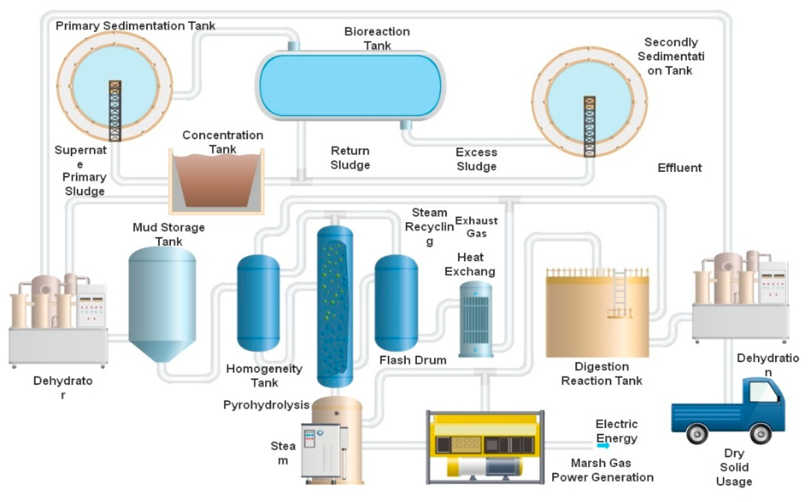
Water Free Full Text Environmental Sustainability Assessment Of A New Sewage Treatment Plant In China Based On Infrastructure Construction And Operation Phases Emergy Analysis Html
Safety in Wastewater Treatment Plants. In industry, safety comes first - a safe and healthy environment is the most important thing that a company can offer their employees. 27 Figure 10: Process Flow Diagram for Building 1 Wastewater Treatment.

Flow Sheet Of Sewage Treatment Plant Flow Diagram Of Wastewater Treatment Plant Youtube
Traditional design procedures for wastewater treatment systems attempt to minimize total capital cost by considering steady state concepts for unit processes and The treatment plant model includes primary clarification, aeration, secon-dary clarification, gravity thickening and anaerobic digestion .

Municipal Sewage Treatment Plant No 2
Process flow diagrams (PFDs) are used in chemical and process engineering. Generally, a Process Flow Diagram shows only the major equipment and doesn't show details. PFDs are used for visitor information and new employee training.

Wwtp Process Flow Chart Pdf Sewage Treatment Biodegradable Waste Management
Although effective in wastewater treatment, the use of inorganic metal coagulants for microalgae Microalgae are the preferred crop for the production of biodiesel. Microalgae are micro-plants that have the Filtration of microalgae, which includes techniques such as dead-end filtration and cross flow...
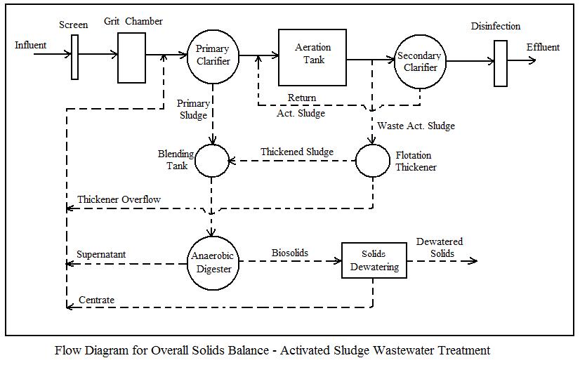
Activated Sludge Calculations In A Solids Mass Balance Spreadsheetlow Cost Easy To Use Spreadsheets For Engineering Calculations Available At Engineering Excel Spreadsheets
Figure 4 process flow diagram for a typical oxidation ditch. Oxidation ditches tend to operate in an extended aeration mode consisting of long hydraulic and solids retention Currently, the wastewater treatment plant in Ocoee, Florida accepts an average flow of 1.1 to 1.2 MGD.

Typical Process Flow Diagram Of A Wastewater Treatment Plant Wwtp Download Scientific Diagram
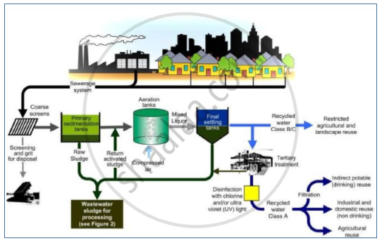
2.2 Wastewater Treatment Plants WWT can generally be broken down into four seemingly simple processes: 1. Primary treatment 2. Secondary treatment 3. Tertiary treatment 4. Sludge treatment. A flow diagram for the activated sludge process is shown in Figure 3. The activated...

Effluent Treatment Plant Process Inward Textile Industry Achivementlearn
Wastewater treatment is a process used to remove contaminants from wastewater or sewage and convert it into an effluent that can be returned to the water cycle with acceptable impact on the...
Wastewater Treatment Pfd Free Wastewater Treatment Pfd Templates
The municipality has 27 wastewater treatment plants which discharge their final effluent into the nearest river in the respective areas. The receiving rivers are exposed to contamination. To avoid or reduce such contamination, the final treated effluent must have acceptable levels of compliance to...
Wwtp Process Flow Diagram Pdf Environmental Issues With Water Chemical Processes
The soap manufacturing process flow diagram is shown in figure 1. Receiving Storage Transfer Fatty Acid Caustic Soda Sodium Chloride (Salt) Sodium The degree of treatment can be determined by comparing the influent wastewater characteristics to the required effluent wastewater characteristics.

Konya Wastewater Treatment Plant Flow Diagram 1 3 Youtube
Figure 5.6 . Process flow diagram of wastewater treatment plant including a mass balance (gpm) based on 24 average during continuous operation. The flow then enters a reverse osmosis plant containing three parallel streams designed at 50% flow enabling continuous operation.
Draw Flow Sheet Diagram And Explain The Process Of Industrial Waste Water Treatment Environmental Studies Shaalaa Com
Onondaga County Department Of Water Environment Protection

Petropath Fluids India Pvt Ltd

H H Restoration Water Treatment Plant Water Treatment Wastewater Treatment Plant
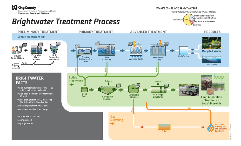
Wastewater Treatment Process King County

Flow Diagram Showing The Process Of Wastewater Treatment Plant Which Download Scientific Diagram
Wastewater Treatment Waterh20
Flow Diagram

Process Flow Diagram Of The Mudor Waste Water Treatment Plant Download Scientific Diagram
Municipal Wastewater Treatment Plants Treatment Process Management System

Flow Diagram Of The Industrial Wastewater Treatment Plant Of The Download Scientific Diagram

Distributed Control Systems For A Wastewater Treatment Plant Architectures And Advanced Control Solutions Intechopen
1
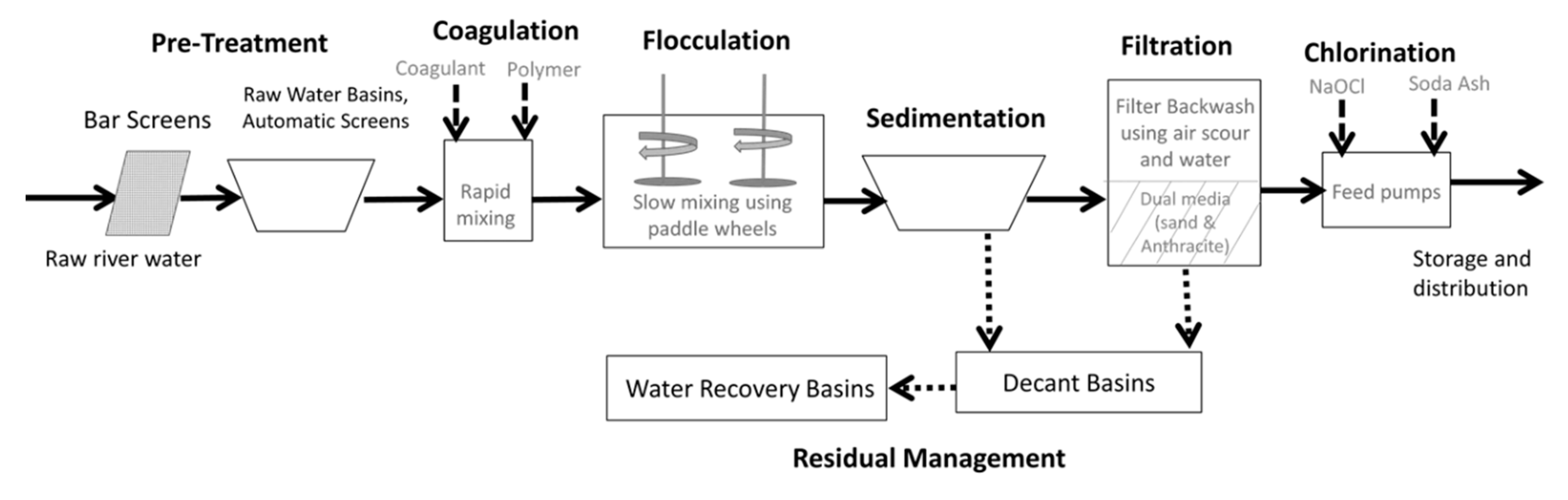
Water Free Full Text Design Aspects Energy Consumption Evaluation And Offset For Drinking Water Treatment Operation Html

Figure 1 From Sewage Management And Its Benefits To Man Semantic Scholar

Learn How Akron Treats Wastewater City Of Akron
The Wastewater Treatment Process Coldwater Mi

Waste Water Treatment Voice Of Environment
Onondaga County Department Of Water Environment Protection

Figure 4 From Energy Efficiency Strategies For Sewage Treatment Plant A Case Study In Malaysia Semantic Scholar

Flow Diagram Showing The Process Of Wastewater Treatment Plant Which Download Scientific Diagram
8 Wastewaster Treatment Process Steps Stages Masterflex

Cattle Shed Wastewater Treatment Plant Kanagawa Prefectural Livestock Industry Technical Center
Diagram Process Flow Plant Treatment Of Sewage Dwg Block For Autocad Designs Cad
0 Response to "41 wastewater treatment plant process flow diagram"
Post a Comment