41 locknetics maglock wiring diagram
Electrical Instructions: ... Do not install a diode in parallel with any magnetic lock. A diode ... Retrofits Discontinued Locknetics 350+.3 pages WIRING AND TECHNICAL INFORMATION Form 39873 2 10/13/2003 MBS: (Magnetic Bond Sensor - indicates lock status, shown unlocked: changes state when a good magnetic bond is indicated) WHITE: C. WHITE: N.O. (RATING:0.250A@30VDC) NOTE: POLARITY IN THIS CASE DOES NOT MATTER. IT IS SHOWN AS A SUG-GESTION TO KEEP WIRING WITHIN A SYSTEM CONSISTENT. MBS ...
Locknetics Maglock Wiring Diagram. 17.09.2018 17.09.2018 1 Comments on Locknetics Maglock Wiring Diagram. Locknetics offers many sizes of each. Herculite door brack- connections (see wiring instructions on next page). Install circuit board(s) (if OUTSWINGING MAGNETIC LOCK with AVS SEE DIAGRAMS ABOVE. PC BOARD.
Locknetics maglock wiring diagram
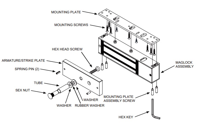
Locks should be installed with wiring covers in the middle, so the magnet in one of the locks must be reoriented. Shown from Exterior MagnetWiring Covers NOTE: Minimum wire gauge 22AWG. 3 1b Reorient Magnet and Board (if necessary) • Remove screws, wiring cover and end blocks. • Remove board. End Block (with screw hole) 6. Continue to fasten mounting plate to heading using remaining screws. Then, reassemble maglock assembly to mounting plate. 7. Route the enclosed wiring harness through the rectangular hole in the mounting plate. Make the electrical connection as shown below. 8. Make sure that armature/strike plate can be shaken slightly. 22 Jun 2020 — Diagram Kawasaki Z650 Kz650 Colour Wiring Loom Diagrams. 390pir Magnetic Locking System Installation And Wiring. Mag Lock Wiring Diagram ...
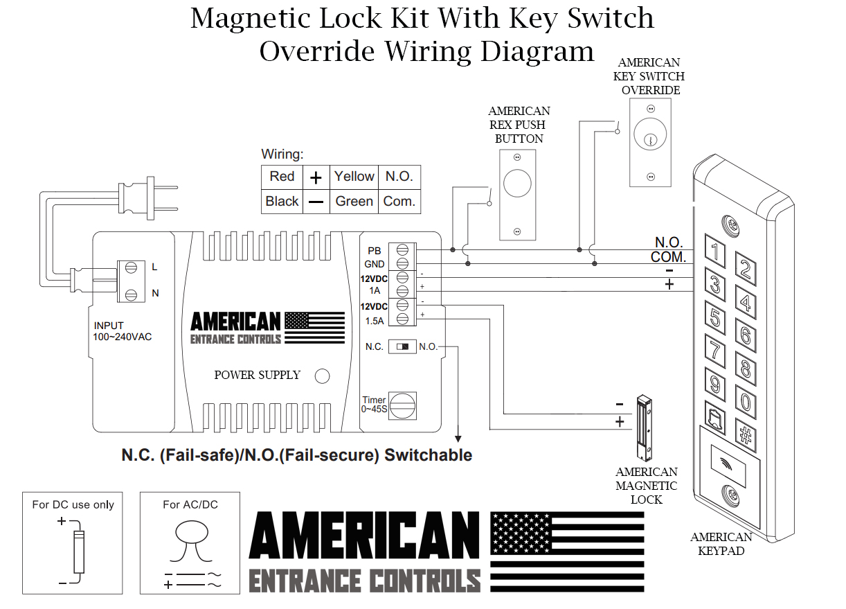
Locknetics maglock wiring diagram. grainger' s got your back. sixteen models cover a full range of needs with 500, 10 lb. assortment of locknetics maglock wiring diagram. delayed egress systems. which triggers a 15 or self- contained unit, designed to meet nfpa life safety code and. delayed egress locks provide a " nuisance cycle" and an " egress cycle. M400 Series Electromagnetic Lock. The M400 Series offers 16 models that are designed to make quick, light work of installation with a bayonet mounting bracket and slide-together components for easy in-field handing and wiring. 1 SPDT voltage output . The SDC ACM-1 Access Control Module is an magnetic lock or electric strike. . (for two door or tamdem applications). The next step is to have a 'fail safe' method of cutting the power to the lock to ensure the Where access control equipment is fitted to a fire escape door which includes an Wiring Break glass units and fire alarm interfaces The FIB provides a switching ... Wiring the Electromagnetic Locking System. In the simple diagram above, you can see that the electricity travels in an unbroken loop. It starts at the "+" (positive) terminal of the power supply, travels through the exit and entry switches, into the positive terminal of the magnetic lock, and out through the negative (-) terminal of the mag back in through the negative terminal of the power ...
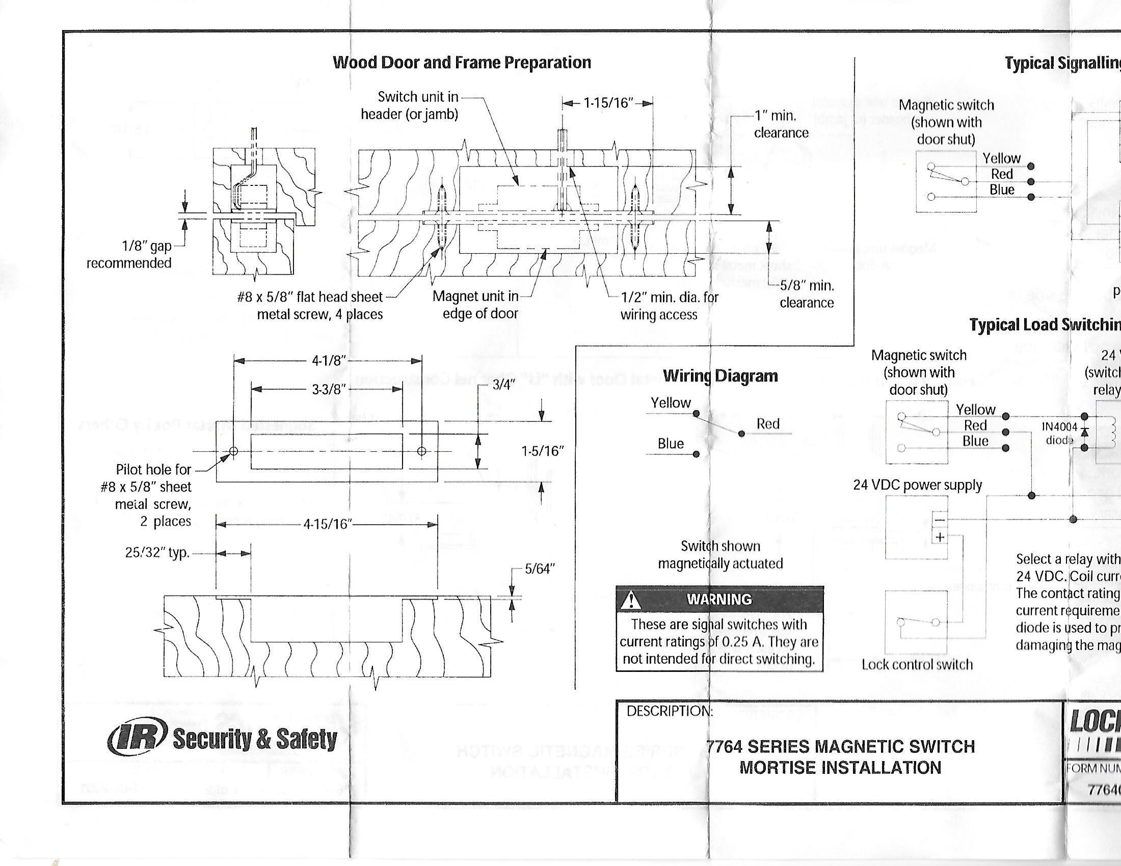
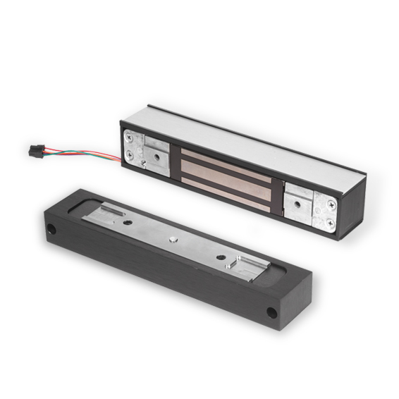
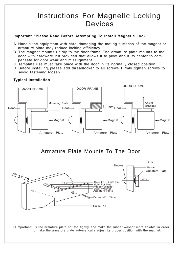
LOCKNETICS 575 Birch Street, Forestville, CT 06010 Phone (860) 5840158 Fax (860) 584-2136 Www.locknetics.com 268M / 268MN MORTISED MAGNETIC LOCK INSTALLATION AND WIRING INSTRUCTIONS The 268M series electromagnetic powerlock is a custom engineered electromagnetic lock designed to be mortise mounted into both the door frame and the door. Wiring for the electromagnet must enter the top of the unit through the wire access hole drilled in the frame header (see template). Be certain provisions can be made to bring the wire through the header into the top of the unit. Frame conditions may require the use of filler plates and/or angle brackets. These items are available from Locknetics. Locknetics Maglock Wiring Diagram. Assortment of locknetics maglock wiring diagram. A wiring diagram is a streamlined standard pictorial depiction of an electrical circuit. It reveals the components of the circuit as simplified forms, and also the power and also signal connections between the tools. A wiring diagram typically offers details regarding the family member… You can purchase our magnetic lock kits at http://www.allsecurityequipment.com/categories.asp?cat=Magnetic+Lock+KitsInstructions on how to wire a magnetic lo...
Locknetics Maglock Wiring Diagram. This manual covers the complete installation and wiring instructions for the following. GF . Make final wiring connections (see Wiring Diagram: on page LOCKNETICS. M I MN MORTISED MAGNETIC LOCK. INSTALLATION AND WIRING INSTRUCTIONS. Birch Street, Forestville, CT. Wiring should be protected by conduit. How to wire a magnetic lock with, backup battery, exit button and key switch. This and other diagram and tutorials are available on our website at; www.there... Locknetics provides the most complete selection of electromagnetic locks in the industry. The GF3000 Series Shear Lock features a patented design offering advances over any Shear Lock on the market. Unique mounting features provide a "floating" action of both the lock assembly and the armature. This design Locknetics Maglock Wiring Diagram Collection. locknetics maglock wiring diagram - Architectural electrical wiring diagrams show the approximate locations and interconnections of receptacles, illumination, and long-term electric solutions in a building. Adjoining cable routes may be revealed roughly, where particular receptacles or fixtures should get on a typical circuit.
How Do You Wire For Electro Magnetic Lock Wireless Receiver Kits Solidremote Support
Wiring Diagram Sheets Detail: Name: locknetics maglock wiring diagram - Locinox Magmag 2500 9005 Magnetic Lock 600 1200 Lbs In Ral 9005 For Mounting Square Posts And Gate Profiles 1 9 16" Till 3 1 8" 600 Lbs Pulling

Dc 12v Single Door 350kg 700lbs For Door Access Control System Electric Magnetic Lock M350sb With Buzzer Access Control Kits Aliexpress
mag lock wiring diagrams . chexit wiring diagram . lever locks for fire doors . emergency release tool . two single doors with panic bars . two single doors with panic bars . push button release electric strike . HOT ELECTRIC TRIM . is there an rga form? ...

Locknetics Product Catalog Manualzz
WIRING STANDARD FEATURES Operating Voltage The GF3000 will operate only on filtered, regulated 12 or 24 volts DC. Automatic voltage selection circuitry is standard. Automatic Relock Switch (ARS) A built-in relock switch requires the door to be in the closed position before the magnet can be energized. Adjustable Time Delay (ATD)
Locknetics Mg600 Electromagnetic Lock 600lbs
Monitored Maglock Wiring Diagram. Door entry maglock install guide smart security mag ock access control how to wire with a lock magnalock models m32 m62 and m82b installation instructions cables wiring diagram kisi electromagnetic locks manualzz keypad strike architecture basic magnetic system hubpages rgl exml1200 gate monitored external ...

Locknetics Electromagnetic Locks Pentagon 100 Series Manualzz
Locknetics delayed egress maglock manual January 23, 2018 Download >> Download Blocknetics 25S9 Manual Read Online >> Read Online Locknetics 25S9 Locknetics Manual Locknetics Website 390 Locknet Manual 350+ Locknet Wiring Maglock Locknetic Manual 101+ Locknice Manual Maglock Auxiliary Lock Diagram 25S9 Locknetics 25S9, Homebrew Computers, NEC Programming
Network Access Control System Rfid System For Locknetics Double Door Rfid Guard Tour System System Decorsystem Microphone Aliexpress
- WIRING INSTRUCTIONS— Magnetic lock or fail safe strike with button, keypad, maintained button and remote receiver. wired in series Power Supply for fail safe strikes and magnetic locks should be DC. If this is not available you may use an AC power source and wire inline a "Full Wave Bridge" rectifier. This will conver t the AC to DC.

Mem Dol Starter Wiring Diagram Mizzxerraa
trane ac wiring diagram - What is a Wiring Diagram? A wiring diagram is an easy visual representation in the physical connections and physical layout of the electrical system or circuit. It shows the way the electrical wires are interconnected which enable it to also show where fixtures and components may be attached to the system.

Locknetics By Schlage M490g Electromagnetic Gate Lock
8 Connect wiring to board (plus model). 8a Review wiring connections. TB1 TB2 TB3 RED Note: Two MBS plugs are interchangeable. RTD Adjuster Min. Time Max. Time From MBS From MBS From LED From Magnet Polarized Black/Red NO NC C NO NC C DC(+) DC(-) DC Power DPS: 0.25A, 30VDC, Resistive Contacts shown in open-door state MBS: 1A, 30VDC, Resistive
Absupply Net
manufacturer's installation and operation instructions, the Life. Safety Code, ANSI/NFPA 70 and 101, and the local authority having jurisdiction.

Schlage 390g Installation Instructions Pdf Download Manualslib
STEP 4: WIRING Provision must be made to get wiring to the device on the door. Common methods are an electric hinge, door cord, or power transfer device. A model 798-18 Armored Door Cord Kit is included as standard equipment with each 692 TouchBar to facilitate power transfer. Make wiring connections as required by the system wiring diagram.

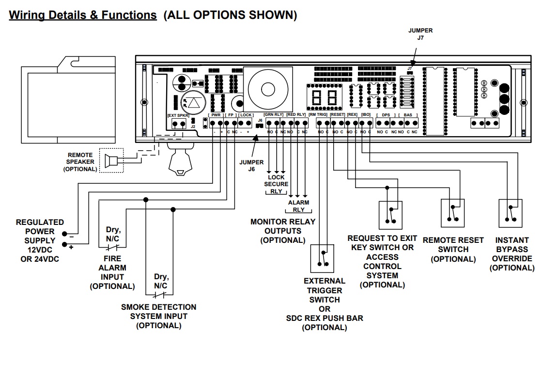
390pir Magnetic Locking System Installation And Wiring
1973 F250 Wiring Diagram Fuel Gauge Wiring Diagram Mins Wiring Diagram Centre is one of the pictures that are related to the picture before in the collection gallery, uploaded by autocardesign.org.You can also look for some pictures that related to Wiring Diagram by scroll down to collection on below this picture. If you want to find the other picture or article about 1973 F250 Wiring Diagram ...
Content Interlinebrands Com
That would be fine. the lock in question is a locknetics 350, however I have tried this with many locks. I put my meter on the MBS terminals and there is no change in state. If it is a wet contact that would explain it however the ppwk has indicated SPDT
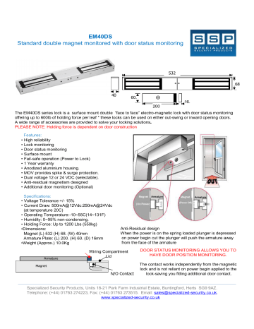
Em40ds Standard Double Magnet Monitored With Door Status Manualzz
Discover the Simplicity of Locknetics Backed by the strength and promise of Allegion, Locknetics provides electromechanical hardware for access control solutions. Designed to fit the challenges of everyday, on the job applications, the Locknetics portfolio, with electric strikes, electro-magnetic locks and access control accessories, offers ...
Schlage Gf3000
Locknetics Maglock Wiring Diagram Free Wiring Diagram. Save Image. Magnetic Door Contact Wiring Diagram Free Wiring Diagram. ... Maglock Wiring Diagram. Save Image. mon Door Kit for Hotels, Magnetic Lock, Fail safe: maglocks. Save Image. Door Release Relay & Typical Installation Sc 1 St .
Ul600lsdm Magnetic Lock Manual Manualzz
Read Mounting Instructions and review this manual. 2. V. Mount the lock in accordance with the Mounting Instructions. DWG T ...
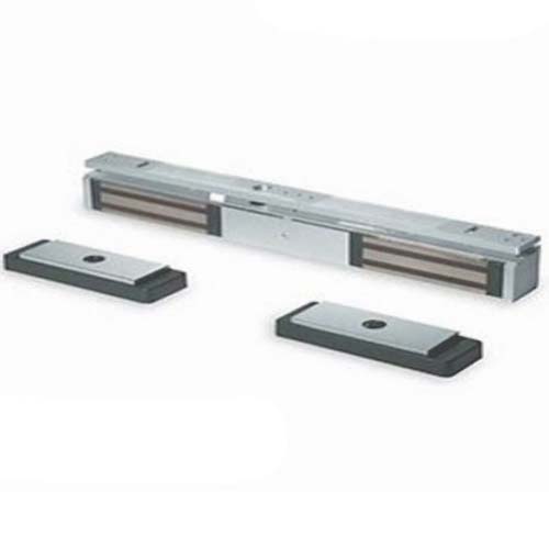
Locknetics Double Mini Maglock M422
22 Jun 2020 — Diagram Kawasaki Z650 Kz650 Colour Wiring Loom Diagrams. 390pir Magnetic Locking System Installation And Wiring. Mag Lock Wiring Diagram ...

Wiring A Maglock With A Rex Device Prodatakey Inc
6. Continue to fasten mounting plate to heading using remaining screws. Then, reassemble maglock assembly to mounting plate. 7. Route the enclosed wiring harness through the rectangular hole in the mounting plate. Make the electrical connection as shown below. 8. Make sure that armature/strike plate can be shaken slightly.

Locknetics 101 Delayed Egress Maglock System
Locks should be installed with wiring covers in the middle, so the magnet in one of the locks must be reoriented. Shown from Exterior MagnetWiring Covers NOTE: Minimum wire gauge 22AWG. 3 1b Reorient Magnet and Board (if necessary) • Remove screws, wiring cover and end blocks. • Remove board. End Block (with screw hole)
Installing A Maglock On A Storefront Door How To Guide

Pi Manufacture

Locknetics 392 Double Electromagnetic Lock

Troubleshooting Electronic Security Hardware Assa Abloy

Wiring Maglock Electromagnetic Door Lock Push Button Power Supply 12v Youtube

Dynalock 2050 Us26 Maglock Single Electromagnetic Lock Outswing Locknetics 350 Exact Retrofit 12 24vdc
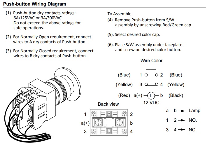
Locknetics Ipb 300 Mushroom Push Button
Magnetic Door Lock
Maglock Failure No Software Notification R Accesscontrol

Fpc 5019 One Door Access Control Inswinging 1200lbs Kit Fpc Security Maglocks Kit Visionis
Dortronics Plc Man Trap Interlock 2 Door System
How Do You Wire For Electro Magnetic Lock Wireless Receiver Kits Solidremote Support
Absupply Net
1
Dynalock Com
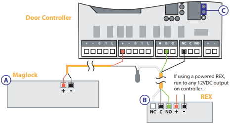
Wiring A Maglock With A Rex Device Prodatakey Inc
Locknetics Maglock Wiring Diagram Mizzxerraa

Locknetics 390 395935 Control Board For Locknetics 390 High Security Electromagnetic Lock
Magnetic Door Locks Mir6s Mir6b Mircom
Sdc 1511snakv Delayed Egress Magnetic Lock 1650lbs
Mfsales Com

Locknetics 392 Dsm Mbs Electromagnetic Lock
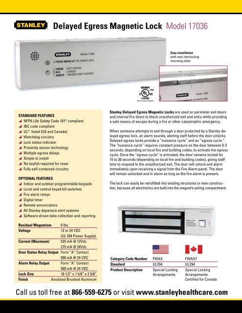
Delayed Egress Magnetic Lock Model 17036
0 Response to "41 locknetics maglock wiring diagram"
Post a Comment