41 it is acceptable for arrows to cross one another in a network diagram.
It is acceptable for arrows to cross one another in a network diagram. True The backward pass through a project network determines slack or how long an activity can be delayed without impacting the completion date of the project. It is acceptable for arrows to cross one another in a network diagram. ... Arrows can cross over each other. AACSB: Reflective Thinking Bloom's: Comprehension Learning Objective: Constructing a Project Network Level: Easy 73. The forward pass through a project network determines the critical path. FALSE The forward pass starts with the first ...
Question 5 1 / 1 pts It is acceptable for arrows to cross one another in a network diagram. True False Arrows on networks indicate precedence and flow. Arrows can cross over each other. ... Arrows can cross over each other. Question 6 1 / 1 pts When creating a project network, your primary input will be the Project Charter.
It is acceptable for arrows to cross one another in a network diagram.
as a workaround, if you need the visual element, you can create an arc as a custom shape with connection points. It adds some extra steps to the workflow, because you have to draw lines to the connect to the arc, and then another to continue to the entity. But, you can then move the 'cross over' around and lines will stay connected. after moving : Network diagrams are used to show how a large project or task can be broken down into a logical series of subtasks. They provide another way to analyze company projects. Network diagrams can be used to: Act as documentation for internal/external communication, onboarding, planning, etc. And so much more! pair with a double headed arrow. Write the dependent variable. From each independent variable, draw a straight, single headed arrow shooting into the dependent variable. Finally, make a notation for a residual variable and draw an arrow from it into the dependent variable. Figure 1 shows this path diagram for LAWYER.
It is acceptable for arrows to cross one another in a network diagram.. A flowchart is the graphical or pictorial representation of an algorithm with the help of different symbols, shapes, and arrows to demonstrate a process or a program. With algorithms, we can easily understand a program. The main purpose of using a flowchart is to analyze different methods. Several standard symbols are applied in a flowchart: It is acceptable for arrows to cross one another in a network diagram. True False. true. It is possible for a project network to have more than one critical path. True False. true. Lags can be used to constrain the start and finish of an activity. ... (more than one dependency arrow flowing from them). True False. It is acceptable for arrows to cross one another in a network diagram. True. The forward pass through a project network determines the critical path. False. The backward pass though a project network determines how long an activity can be delayed without impacting the completion date of the project. True. Sep 21, 2020 — A project network diagram is one such tool that helps simplify a ... That means don't clutter the page with arrows that cross one another.
24) It is acceptable for arrows to cross one another in a network diagram. True False 25) The backward pass through a project network determines slack or how long an activity can be delayed without impacting the completion date of the project. With Creately, you can use one of the multiple network diagram templates available. Once you select a diagram template; Add relevant equipment (by inserting symbols): As shown above, Creately loads the relevant shapes, tools, arrows etc. You can begin by inserting computers, servers, routers, firewalls etc on the page. Shading specific areas of a diagram might look aesthetic to the eye, but this practice is not acceptable in biology. Hence, the advice is to AVOID at all cost. Try to draw the diagram on a single stroke of the pencil. Multiple strokes need to be avoided at all possible costs. Labeling intersections aren't tolerated in biological diagrams. AVOID. The 4 Types of Relationships in Precedence Diagramming Method. In order to complete the network diagram of a project with the method 4 types of relationships between the activities are used. These relationships are: Finish-to-Start, Start-to-Start, Finish-to-Finish, Start-to-Finish. Let's go over each type of dependency.
14 One Load Per Line Two loads must not be connected in series on one line of a line diagram. If the two loads are connected in series, then the voltage between L1 and L2 must divide across both loads when S1 is closed. The result is that neither device receives the entire 120 V necessary for proper operation. The critical path is the shortest path through a network and indicates activities that cannot be delayed without delaying the project. TRUE. ... Arrows can cross over each other. 72. It is acceptable for arrows to cross one another in a network diagram. FALSE. 73. The forward pass through a project network determines the critical path. It is acceptable for arrows to cross one another in a network diagram. True False Arrows on networks indicate precedence and flow. Arrows can cross over each other. References True / False Difficulty: 1 Easy TF Qu. 102 (Static) ... If a network has more than one critical path but noncritical activities have from STC COM135 at Miami University. ... It is acceptable for arrows to cross one another in a network diagram . ... It is acceptable for arrows to cross one another in a network diagram. True False.

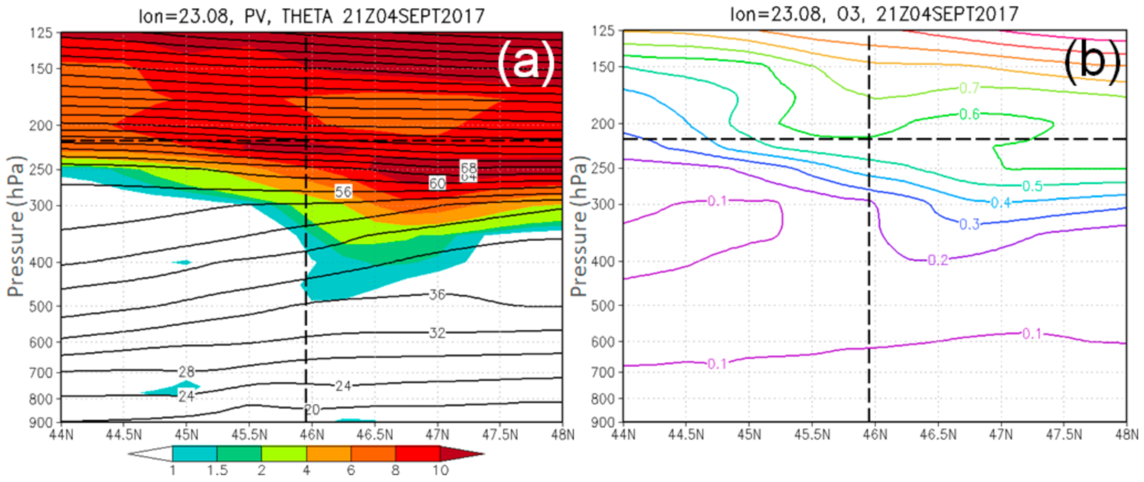
Atmosphere Free Full Text Study Of Clear Air Turbulence Related To Tropopause Folding Over The Romanian Airspace Html
Which of the following represents an activity on an AOA project network? A. An arrow B. A line C. A node D. Both A and B are correct E. A, B, and C are all correct. A. An arrow ... It is acceptable for arrows to cross one another in a network diagram. T/F. ... The _____ method for creating project networks is sometimes called the Precedence ...
The tree diagram (see Section 7.9) when used in the planning format is a very useful precursor for making an arrow diagram. It provides an overview of the stages of a project and the tasks (and their dependencies) that make up the project. If it strongly advised that a tree diagram is completed to provide the essential input for the arrow diagram.
The project network is a visual flow diagram of the sequence, interrelationships, dependencies and timing of all the activities that must be accomplished to complete the project. Both the WBS and the work packages will include the duration of the activity. ... It is acceptable for arrows to cross one another in a network diagram. TRUE. The ...
Predecessors are shown towards the arrow tail while successors are shown towards the arrow head. Sub-network - It is simply called as a subnet. It is a subdivision or a part of a complete Project Network Diagram. Dependencies - A Successor (dependent node) can have more than one predecessors. Similarly a predecessor can have more than one ...
Some flow charts may just have an arrow point to another arrow instead. These are useful to represent an iterative process (in Computer Science this is called a loop). A loop may, for example, consist of a connector where control first enters, processing steps, a conditional with one arrow exiting the loop, and one going back to the connector.
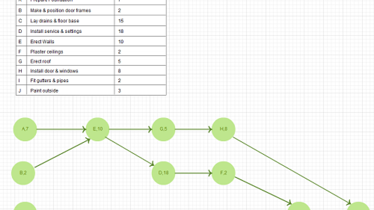
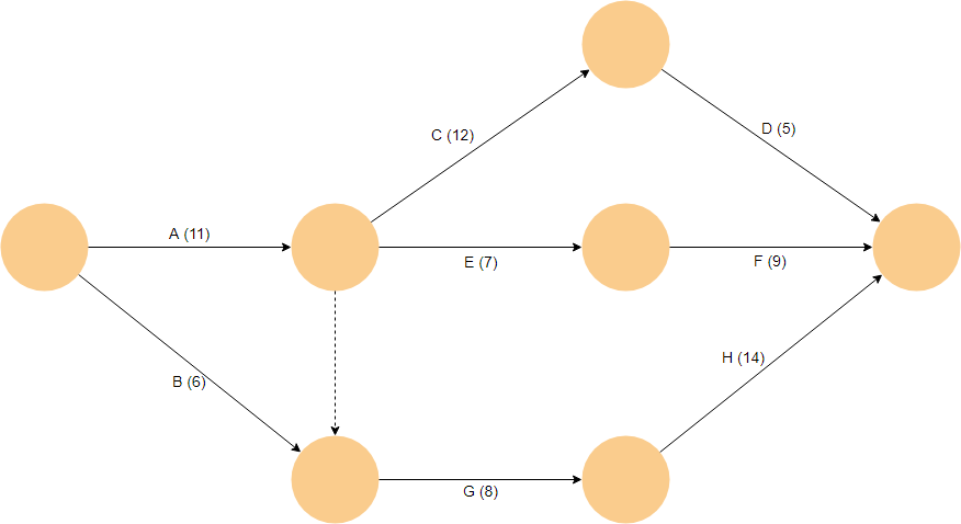
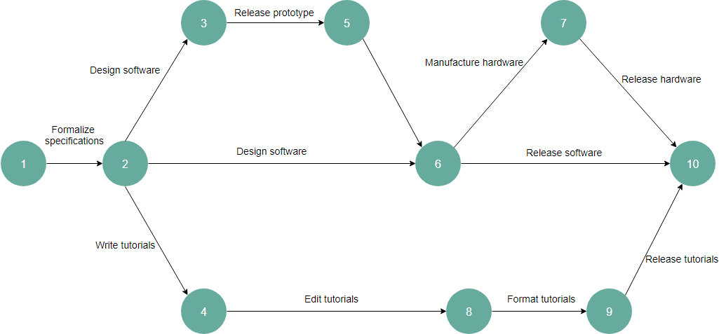
One way to get organized is by using a network diagram. This is a tool for visualizing activities over the course of the entire project. There are two main types of network diagrams: the arrow diagram and the precedence diagram. Let's take a look at the former, also called activity on node or activity on arrow.
TikZ and pgf Manual for version 1.18 \tikzstyle{level 1}=[sibling angle=120] \tikzstyle{level 2}=[sibling angle=60] \tikzstyle{level 3}=[sibling angle=30]
Arrow Diagram Procedure . Materials needed: Sticky notes or cards, marking pens, and large writing surface (newsprint or flipchart pages). Drawing the Network. List all the necessary tasks in the project or process. One method is to write each task on the top half of a card or sticky note. Across the middle of the card, draw a horizontal arrow ...
there are two types of notations used in the network diagram. They are as under,. 1. ... Avoid Looping and crossing of activity arrows by repositioning.72 pages
... diagram, how to define the importance of the critical path in a project network, ... Precedence Diagrams, Activity on Arrow, PERT, Range Estimating, ...
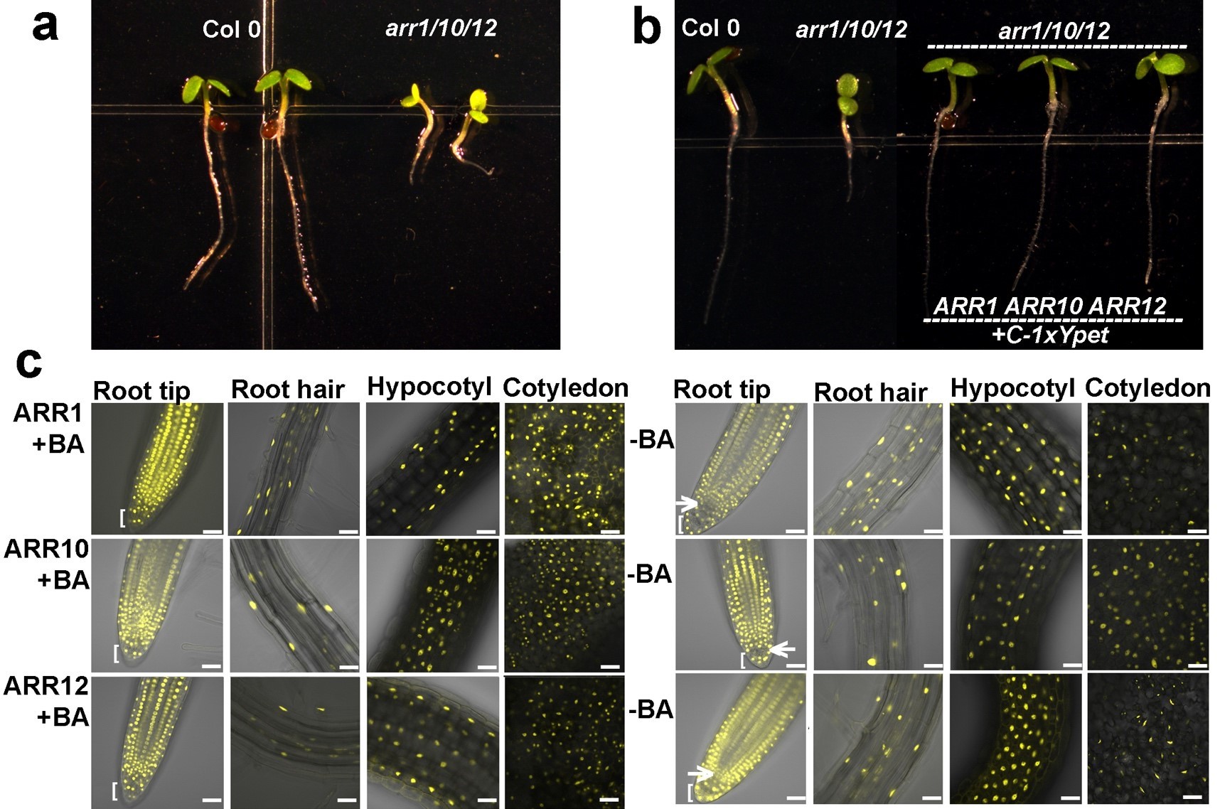
A B Arr Mediated Cytokinin Transcriptional Network Directs Hormone Cross Regulation And Shoot Development Nature Communications
Table 1. Table of Visio shapes that map to Process Designer objects for Basic Shapes stencil. Visio Shape. Designer Object. Triangle. General step. Square. General step. Pentagon.
A good project manager is familiar with either representation. Example 10-1: Formulating a network diagram. Suppose that we wish to form an activity network ...

Building A Ci Cd Pipeline For Cross Account Deployment Of An Aws Lambda Api With The Serverless Framework Aws Devops Blog
The project of budgeting can be displayed in a network or project graph by an arrow diagram. Jobs are shown as arrows leading from one node to the other as in Figure 2.
Network Layout •Next step is to estimate pipe sizes on the basis of water demand and local code requirements. •The pipes are then drawn on a digital map (using AutoCAD, for example) starting from the water source. •All the components (pipes, valves, fire hydrants) of the water network should be shown on the lines.
network traffic. It is software technology that permits for the grouping of network nodes that is connected to one or more network switches into a single logical network. By permitting logical aggregation of devices into virtual network segments, VLAN's offer simplified user management and network resource access controls for switched network
pair with a double headed arrow. Write the dependent variable. From each independent variable, draw a straight, single headed arrow shooting into the dependent variable. Finally, make a notation for a residual variable and draw an arrow from it into the dependent variable. Figure 1 shows this path diagram for LAWYER.
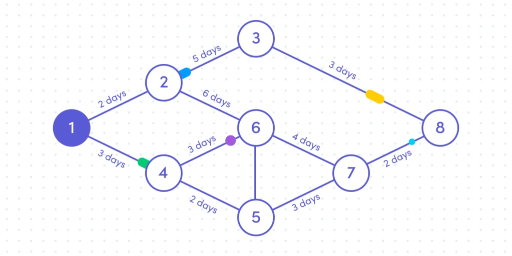
Network diagrams are used to show how a large project or task can be broken down into a logical series of subtasks. They provide another way to analyze company projects. Network diagrams can be used to: Act as documentation for internal/external communication, onboarding, planning, etc. And so much more!
as a workaround, if you need the visual element, you can create an arc as a custom shape with connection points. It adds some extra steps to the workflow, because you have to draw lines to the connect to the arc, and then another to continue to the entity. But, you can then move the 'cross over' around and lines will stay connected. after moving :














0 Response to "41 it is acceptable for arrows to cross one another in a network diagram."
Post a Comment