40 3 phase phasor diagram
Calculate phase current; Phase current = 250003 x 415 x 0.8 Phase current = 25.1 Amps cos-10.8=36.87 I = 25.1 ∠36.87° Amps. Calculate the stator reactive voltage drop IXs; Voltage drop = IaXs 25.1 x 4 ∠36.87° + 90° Voltage drop (IXs) = 100.4 ∠126.87° volts voltage and phase measurement (relative to the appropriate reference), you can measure a phasor value. With a two channel oscilloscope, you have the ability to trigger on each waveform and electronically switch (chop or alt) between them as well. A block diagram of a oscilloscope has now become as shown in figure 10.
Phasor diagram of the three phase system ... Fig. 1 shows the corresponding phasor diagram of the above mentioned system. 2013IEEE 8th International Conference on Industrial and Information ...

3 phase phasor diagram
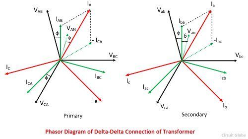
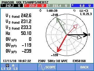
In physics and engineering, a phasor (a portmanteau of phase vector), is a complex number representing a sinusoidal function whose amplitude (A), angular frequency (ω), and initial phase (θ) are time-invariant.It is related to a more general concept called analytic representation, which decomposes a sinusoid into the product of a complex constant and a factor depending on time and frequency. A three-phase transformer is built for a specific connection and voltage transformation and the unit will have a nameplate with the internal connections shown. When a single unit or bank of three is used, there are four types of connections. The four basic connections are: Y-Y, Y-∆, ∆-Y, and ∆-∆. The first symbol indicates the connection of the primary, and the second symbol is the ... Phasor diagram display The most powerful tool on Fluke's three phase analyzers to make this check is the phasor diagram display. In one screen, you can quickly see whether you have connected up the voltage and current in the right sequence and that the current sensors are correctly measuring the direction of the current entering the load or ...
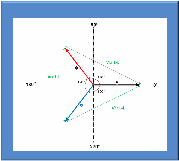
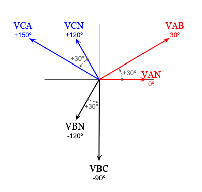
3 phase phasor diagram. The key to understanding three-phase is to understand the phasor diagram for the voltages or currents. In the diagram at the right, a, b and c represent the three lines, and o represents the neutral. The red phasors are the line or delta voltages, the voltages between the wires. The blue phasors are the wye voltages, the voltages to neutral. "vector-algebra," phasor diagrams are combined with algebraic expressions to explain, in simple terms, how currents are calculated in the respective three phase circuits. •Phasor diagrams require a circuit di agram. The phasor diagram… has a indeterminate or vague meaning unless it is accompanied by a circuit diagram. •The assumed directions and polarities are not critic al, as the phasor diagram will confirm if the assumptions were correct, and provide the correct magnitudes and phase relations. Jun 10, 2020 — A three-phase system consists of three sinusoidal AC voltages and currents of identical frequency. Having 6 or more waveforms plotted on the ...
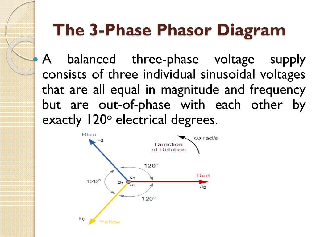
Ppt Phasor Diagrams And Algebra Powerpoint Presentation Free Id 2459890. A three phase phasor diagram b symmetrical six scientific understanding voltage pacific power source of the system star connection in 3 relation between line cur circuit globe side and with balanced phasors systems introduction to ac circuits informit electrical a2z ... 3.7 Voltage and Current Phasors in Three-Phase Systems. As can be seen in equations 3.42, 3.43, and 3.44, the voltage in Phase 1 reaches a maximum first, followed by Phase 2 and then Phase 3 for sequence 1, 2, 3. This sequence should be evident from the phasor diagram of the three-phase source where the phasors should pass a fixed point in the ... Construct phasor diagrams of three-phase sources and loads. Identify the time and phasor plots of a three phase set of voltages and currents. 2/4/2016 2 Double Subscript Notation 3 Lesson 4_et332b.pptx Sources and voltage drops are defined by the terminal letter. Voltage drop Three Phase Power Review ... In a three phase power system there are three voltage phasors, separated by 120 electrical degrees. ... Up to this point the three ...
In the phasor one the direction of the armature current is opposite in phase to that of the excitation emf. It is usually customary to omit the negative sign of the armature current in the phasor of the synchronous motor so in the phasor two we have omitted the negative sign of the armature current. In this video, phasor, and Phasor Diagram for AC circuits have been explained. And at the end, voltage and current relationship between the basic circuit ele... The phasor diagram… has a indeterminate or vague meaning ... Let's try placing phasor representations of the quantities seen from this 3 phase.33 pages Phasors and Phasor Algebra. July 3, 2015. By Administrator. The 'Phasor' is defined as "The complex number in the polar form with which we can analyze the circuit". It is a vector quantity. In this vector representation we use Cartesian plane. The Y axis represents the magnitude and phase angle of the waveform in the form of imaginary ...
Phasor Diagrams Show Phase Difference. A phasor diagram is used to show the phase relationships between two or more sine waves having the same frequency. Section 5.2 showed a phasor continually rotating, but in use phasor diagrams are static. Imagine that the phasors are rotating in an anticlockwise (counter clockwise) direction.
Electricity and Three phase power: Voltage and current "Line to Neutral", "Line to Line", and Phasor Diagrams. My Patreon page is at https://www.patreon.co...
3 Phase Induction Machine: Constructional Features and Principle of Operation: Download: 30: 3 Phase Induction machine: Equivalent Circuit: ... Equivalent Circuit and Phasor Diagram: Download: 39: Synchronous Machines: OC and SC Test: Download: 40: Synchronous Machines: Power Angle Relationship, V and Inverted V Curves:

Electrical Engineering Ch 13 3 Phase Circuit 20 Of 42 What Is The Phase Diagram Of A Y Delta Youtube
The 3-Phase Phasor Diagram Previously we have only looked at single-phase AC waveforms where a single multi-turn coil rotates within a magnetic field. But if three identical coils each with the same number of coil turns are placed at an electrical angle of 120 o to each other on the same rotor shaft, a three-phase voltage supply would be generated.
Construct phasor diagrams of three-phase sources and loads. Identify the time and phasor plots of a three phase set of voltages and currents.
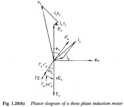
Phasor Diagram of Three Phase Induction Motor . In a 3-phase induction motor, the stator winding is connected to 3-phase supply and the rotor winding is short-circuited. The energy is transferred magnetically from the stator winding to the short-circuited, rotor winding. Therefore, an induction motor may be considered to be a transformer with a ...
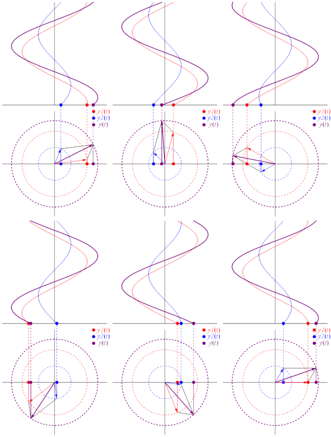
eq 3: Addition of two complex AC signals. With A 3 and Φ 3 depending on A 1, A 2, Φ 1, Φ 2 being the new parameters amplitude and instant phase of the resulting signal y 3 (t).. In this tutorial, we will introduce a new representation of sine waveforms which is graphical and it is known as the phasor representation.The first section will present this new concept and clarify where it comes from.
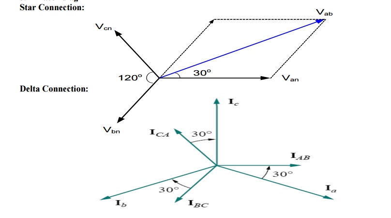
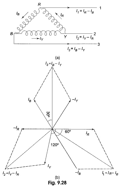
Given a balanced three-phase system, the currents flowing into the delta-connected load can be defined by The resulting phasor diagram relating the line currents to the delta-connected load currents follows the same pattern as the delta-connected source.
The phasor diagram… has a indeterminate or vague meaning unless it is accompanied by a circuit diagram. The assumed directions and polarities are not critical, as the phasor diagram will confirm if the assumptions were correct, and provide the correct magnitudes and phase relations. These two complementary diagrams (circuit and phasor) are ...
Fig 5.3.1 Showing Phase Relationship with Phasors Fig 5.3.1 shows how a phasor diagram is used to illustrate the phase difference between waves 1 and 2. The main value of phasor diagrams is that they can be used, not only to represent waveform diagrams, but also in carrying out calculations involving ac waves. The calculations can involve any of
Time phasor diagrams for one phase winding under no-load and loaded conditions are shown in Fig. 9.17 A and B, respectively, and in each case the time phasors of the flux linkage have been shifted to the right to avoid congestion with the voltages and current.These flux phasors can be compared with the space vectors shown in Fig. 9.10.Once again, resistance has been neglected in the interests ...
These results may also be obtained graphically from the phasor diagram shown in figure (3). Fig.3: Phasor Diagram showing phase and line voltages. Star Connection Line and Phase Currents. Let us consider the system of the figure (4), which is balanced Y-Y, three-phase, four wire system if the source voltages are given by (1).
Determine Phase Rotation via Phasor Diagrams. There is still a problem that I find in most of my classes…phasor rotation is NOT depicted by waveform drawings; they're depicted in phasor diagrams. Many of my students can't determine the correct rotation with typical phase rotation notations on a drawing like the following:
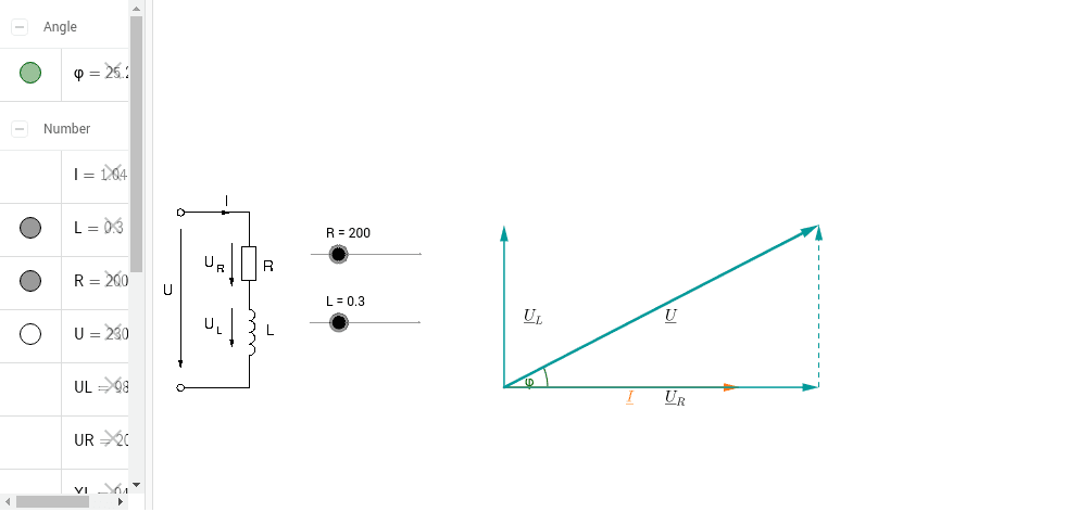
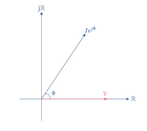
Phasor Diagrams. It is sometimes helpful to treat the phase as if it defined a vector in a plane. The usual reference for zero phase is taken to be the positive x-axis and is associated with the resistor since the voltage and current associated with the resistor are in phase. The length of the phasor is proportional to the magnitude of the quantity represented, and its angle represents its ...
A balanced three phase supply can be connected either in star as in figure 2 (a) or in delta as in figure 2 (b). Figure 1(a) - Three phase waveforms VR VB VY Figure 1(b) Phasor Diagram N VR VB VY Figure 2(a) Star-connected supply IP IL VP VL VRY VYB VBR Figure 2(b) Delta-connected supply Id IL VL
Phasor Diagram. The Maxwell’s bridge circuit is said to be in a balanced condition if the phase shifts of inductors and capacitors are opposite to each other. That means Capacitive impedance and inductive impedance are placed opposite to each other in the bridge circuit. The current I3 and I4 are in phase …
Relation Between Phase Current and Line Current in Delta Connection. As in the balanced system the three-phase current I 12, I 23 and I 31 are equal in magnitude but are displaced from one another by 120° electrical. The phasor diagram is shown below: Hence, If we look at figure A, it is seen that the current is divided at every junction 1, 2 ...
A phasor is a special form of vector (a quantity possessing both magnitude and direction) lying in a complex plane. Phasors relate circular motion to simple harmonic (sinusoidal) motion as shown in the following diagram.
Phase Angle. From the phasor diagram, the value of phase angle will be. Power in RLC Series Circuit. The product of voltage and current is defined as power. Where cosϕ is the power factor of the circuit and is expressed as: The three cases of RLC Series Circuit. When X L > X C, the phase angle ϕ is positive. The circuit behaves as RL series ...
Phasor diagram display The most powerful tool on Fluke's three phase analyzers to make this check is the phasor diagram display. In one screen, you can quickly see whether you have connected up the voltage and current in the right sequence and that the current sensors are correctly measuring the direction of the current entering the load or ...
A three-phase transformer is built for a specific connection and voltage transformation and the unit will have a nameplate with the internal connections shown. When a single unit or bank of three is used, there are four types of connections. The four basic connections are: Y-Y, Y-∆, ∆-Y, and ∆-∆. The first symbol indicates the connection of the primary, and the second symbol is the ...
In physics and engineering, a phasor (a portmanteau of phase vector), is a complex number representing a sinusoidal function whose amplitude (A), angular frequency (ω), and initial phase (θ) are time-invariant.It is related to a more general concept called analytic representation, which decomposes a sinusoid into the product of a complex constant and a factor depending on time and frequency.
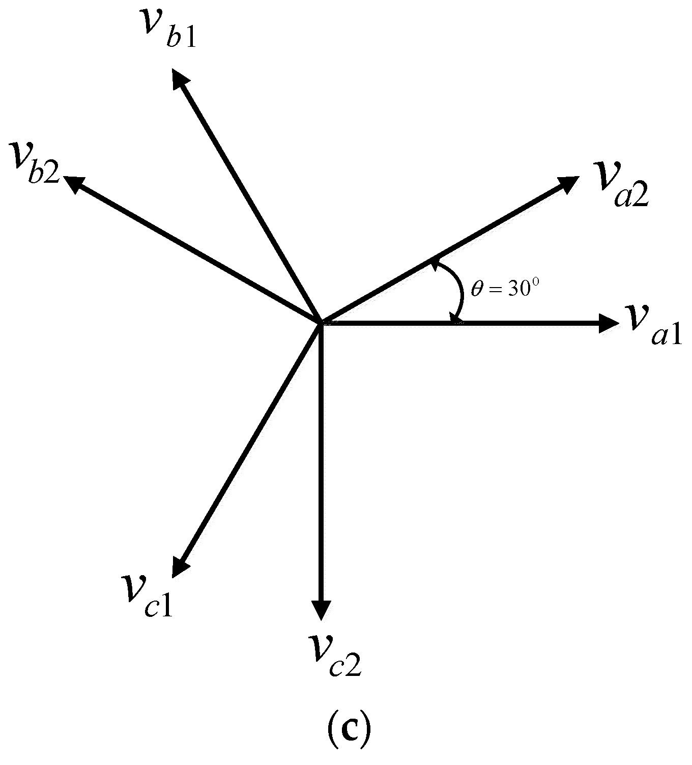
Electronics Free Full Text Systematic Implementation Of Multi Phase Power Supply Three To Six Conversion System Html










0 Response to "40 3 phase phasor diagram"
Post a Comment