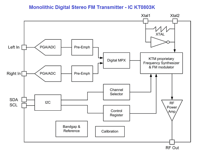
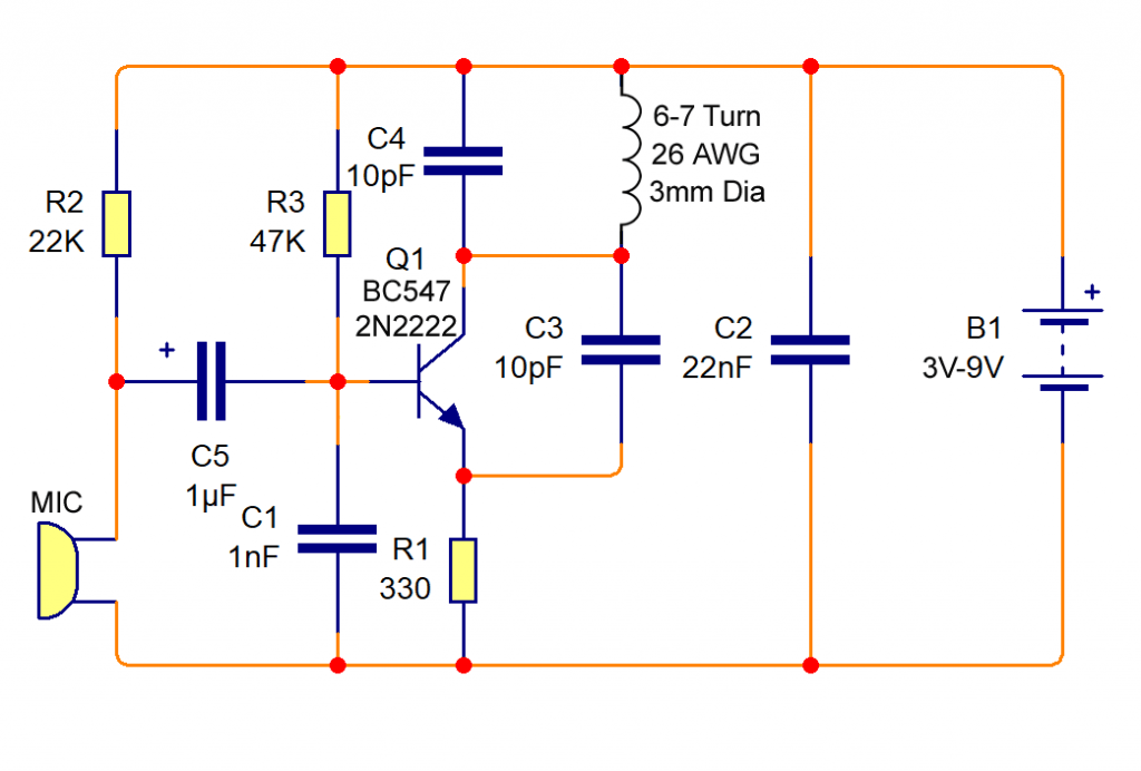
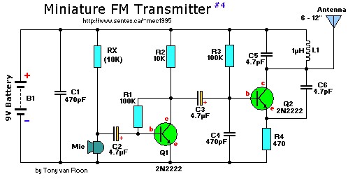
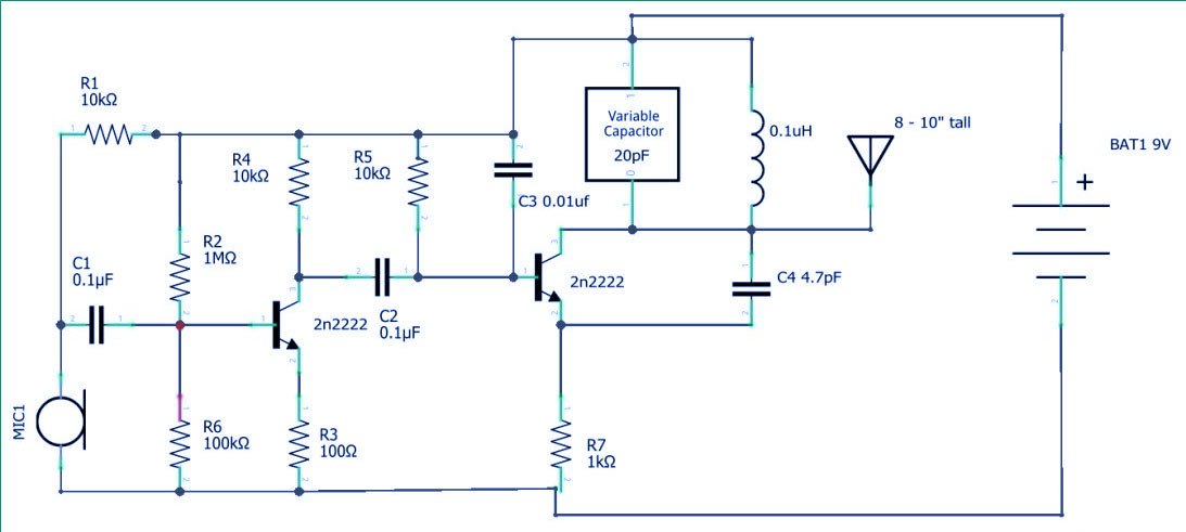
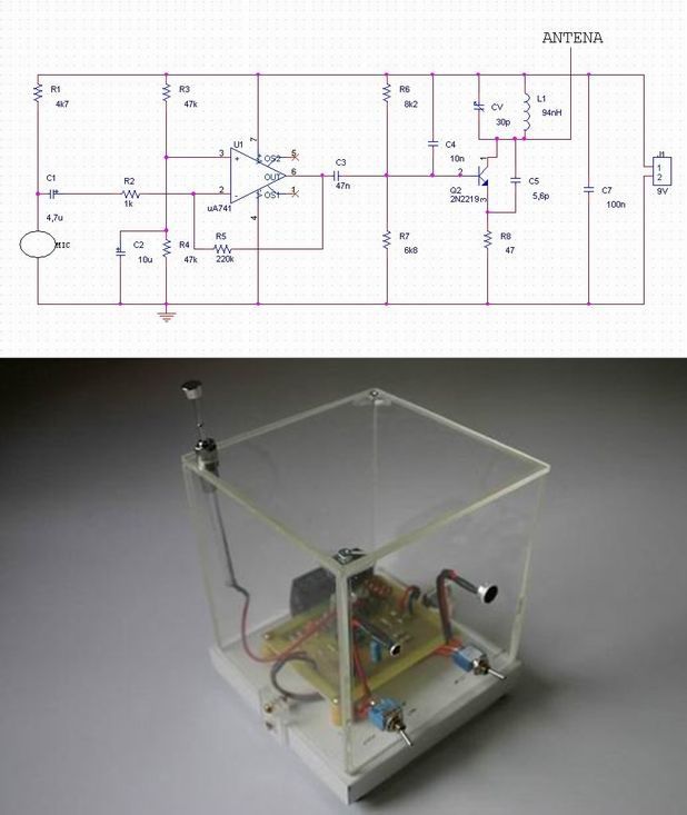
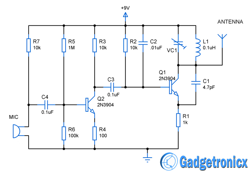
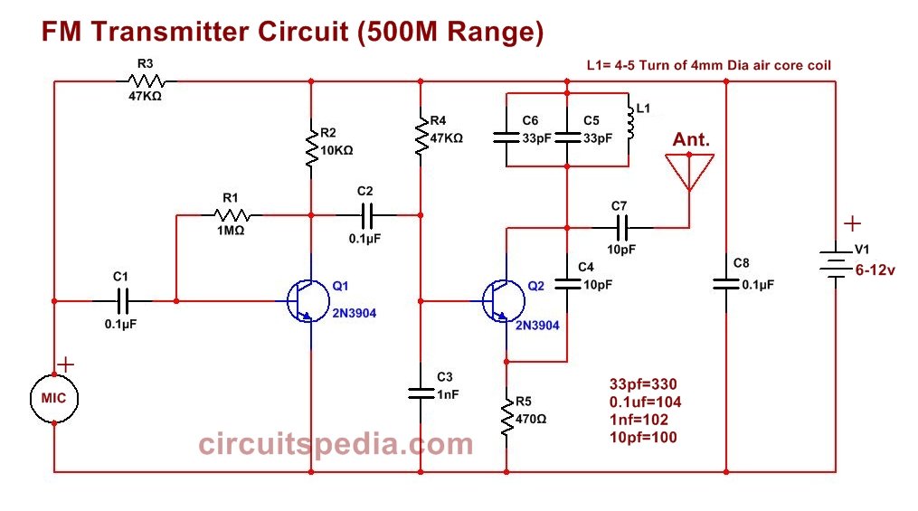
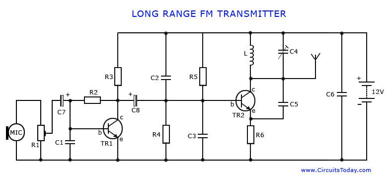
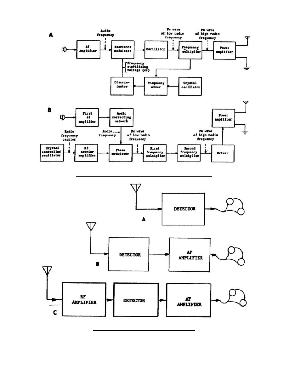
39 fm transmitter block diagram
FM Receiver Working Principle. To easily understand the working principle of FM Receiver, see the block diagram. The first block is the Antenna. The antenna is used to receive the radio signals and intercepted it. The next block is Radio Frequency Amplifier or RF amplifier. The RF amplifier is used to amplify the RF signal received by the antenna. Radio Transmitter Block Diagram. This block diagram of a radio transmitter in a communication system is very simple and basic. It is generalised for AM and FM types of modulation, and consists of four subsystems. Communication is the transfer of meaningful information from one location to another. We start with the conversion of sound waves in ...
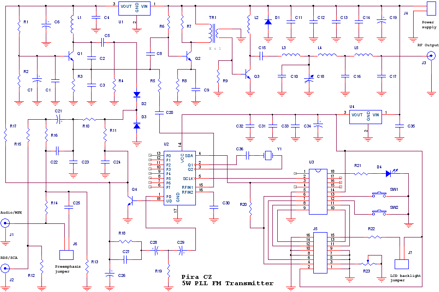
Fig. 1 shows the simplified block diagram of the PLL based FM audio transmitter. The PLL sets the carrier frequency, and the modulation is applied directly at ...

Fm transmitter block diagram
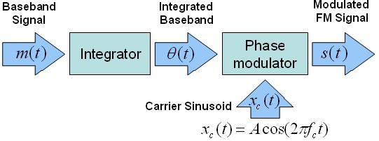
FM Transmitter Block Diagram. As the block diagram above illustrates, the integration of a message signal results in an equation for phase with respect to time. This equation is defined by the following equation: where k f is the frequency sensitivity. Again, the resulting modulation that must occur is phase modulation, which involves changing ... This weekend is our stake conference. We were looking forward to going to the adult session this evening, but an hour before the meeting my wife notifies me she isn't feeling well. Over the next hour this is my thought process and what went down: * We live on the same block as the stake center. * I was stake technology clerk for 15+ years and am well familiar with the building's systems. * I'm also an [extra class amateur radio licensee](https://hamstudy.org/content/how) (ham operator, big time... "A spectrum analyser is not what you need, because it only shows the energy of single channels, over the whole spectrum. However it wont show a spread spectrum signal using direct sequencing or frequency hopping. Try to measure the curents induced in your body instead. This will cover all available technologies for directed energy weapons. Because it measures the effect, not the method used to cause it. Ths is necessary because several technologies are available to cause the effects we see. It ...
Fm transmitter block diagram. The circuit can also be used as a remote control transmitter. FM Demodulator using PLL - This is a good circuit of an FM demodulator with a schematic diagram, a design of FM demodulator, and working of PLL with block diagram. This will definitely be useful for your educational purposes. FM stereo demodulator using AN7415 - Stereo ... It's not a circuit diagram, but a block diagram, which means it can't be used to understand the transmitter at the component level. However it can be used to aid a first level diagnosis of problems, and which circuit board or black box to replace when something fails. Can anyone please provide me a block diagram for spectrum sensing, preferably matched filter detection? I am working on spectrum sensing in cognitive radio. My aim is to detect the presence of primary user which is going to be an FM transmitter. I am using RTL-SDR for receiving the signal. Update: Here's a reference block diagram I cam across from a technical paper https://www.researchgate.net/profile/Eduardo_Avendano_fernandez/publication/295932476/figure/fig3/AS:333565486223362@1456539617543/... A FM transmitter is a device that uses the principles of frequency modulation to broadcast sound supplied at its input. Typical FM transmitter design's usually follow the block diagram below; The signal strength of audio inputs into the transmitter is usually low therefore an amplifier is usually built to bring the signal level up.
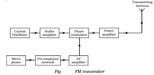
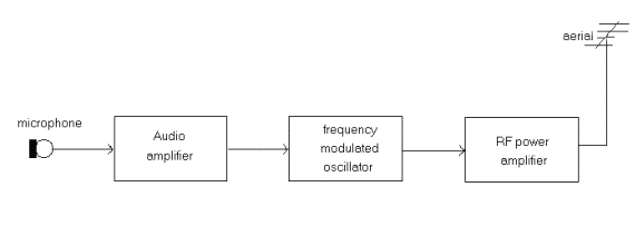
• Draw a block diagram of an FM receiver, showing the frequency and type of signal at each major test point. • Explain the operation and alignment of Foster-Seeley/Ratio, PLL, and quadrature FM detector circuits. • Describe the features of noise-suppressing circuits in an FM receiver. Block Diagram of FM Transmitter. The following image shows the block diagram of the FM transmitter and the required components of the FM transmitter are; microphone, audio pre-amplifier, modulator, oscillator, RF- amplifier, and antenna. There are two frequencies in the FM signal, the first one is the carrier frequency and the other one is ... Block diagram of FM transmitter and receiver and its explanation. FM transmitter. Frequency Modulation is the process in which the frequency of the carrier signal is varied by the modulating signal while the amplitude remains constant. Using Reactance modulator direct method. FM Transmitter Working Principle. The main function of an FM Transmitter Circuit is to transmit the sound using radio waves. So, at first, an FM Transmitter Circuit converts the sound or audio into radio wave then it transmit. You can see, in the block diagram of the FM Transmitter, the first block is the Microphone.
Below figure's show the block diagram of high-level and low-level transmitters. The basic difference between the two transmitters is the power amplification of the carrier and modulating signals. Figure (a) shows the block diagram of high-level AM transmitter. The block diagram of FM transmitter is shown in the following figure. The output of the carrier oscillator is a fairly small AC voltage perhaps 200 to 400. Here we have adapted the same formula by first amplifying the audio signal generating a carrier signal using an oscillating and then modulating the carrier signal with the amplified audio ... Block Diagram of FM Receiver with Explanation. Standard broadcast for FM is 88-108 MHz. The maximum permissible deviation is 200 KHz. In FM the intermediate frequency is 10.7 MHz. In FM the operating frequencies are much higher than that in AM. It additionally contain a de-emphasis and limiter circuit. The method of demodulation is totally ... The FM Transmitter produces a range of VHF from 88 HZ to 108 MHZ. Block Diagram for FM transmitter circuit. Components required for FM transmitter circuit are modulator, oscillator, RF-Amplifier, Audio pre-amplifier, microphone and antenna. The Diagram shows the Block diagram for FM transmitter circuit.
Block diagram of an FM (frequency modulated) transmitter is given on Pic.2.4. Information being transferred, i.e. the modulating signal, is a signal from some LF source. it is being amplified in LF amplifier and then led into the HF oscillator, where the carrier signal is being created. The carrier is a HF voltage of constant amplitude, whose ...
Block diagram of FM transmitter and receiver and its explanation. FM transmitter. Frequency Modulation is the process in which the frequency of the carrier signal is varied by the modulating signal while the amplitude remains constant. Using Reactance modulator direct method. The FM transmitter has three basic sections.
The link: http://www.laughingpoliceman.com/jammers.htm The text: We, at the LPWS have often been accused of being jammers, but this is far from the truth. Admittedly, there is the playing of music on repeaters, but these are usually idle until one of our members comes along with a jolly tune (see the selection for download!). An analogy of what occurs could be the following:- You stand on a river bridge calmly throwing stones into the water, a few anglers a mile or so away hear this a...
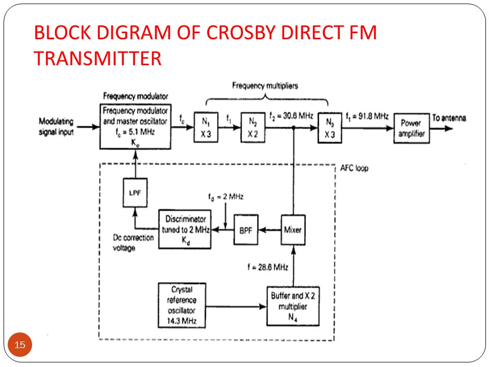
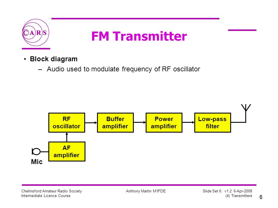
FM Transmitter Block Diagram with Explanation. Block diagram of a low level FM broadcast transmitter is shown in figure. The master oscillator generates the RF signal (carrier) required for modulation. Master oscillator is generally a well defined LC oscillator. The buffer amplifier is used to make the oscillator frequency free from the loading ...

Draw The Block Diagram Of An Fm Receiver And Explain Its Working Sarthaks Econnect Largest Online Education Community
FM transmitter FM Transmitter Block Diagram Direct Method. Using Reactance modulator direct method. The FM transmitter has three basic sections. The exciter section contains the carrier oscillator, reactance modulator and the buffer amplifier.; The frequency multiplier section, which features several frequency multipliers.; The power output section, which includes a low-
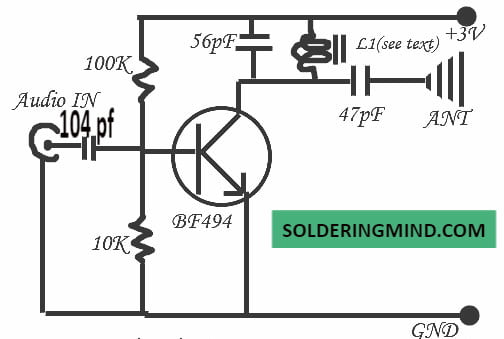
FM Transmitter Circuit Principle: FM transmission is done by the process of audio pre amplification, modulation and then transmission. Here we have adapted the same formula by first amplifying the audio signal, generating a carrier signal using an oscillating and then modulating the carrier signal with the amplified audio signal.
FM Transmitter. FM transmitter is the whole unit, which takes the audio signal as an input and delivers FM wave to the antenna as an output to be transmitted. The block diagram of FM transmitter is shown in the following figure. The working of FM transmitter can be explained as follows.
>A spectrum analyser is not what you need, because it only shows the energy of single channels, over the whole spectrum. However it wont show a spread spectrum signal using direct sequencing or frequency hopping. Try to measure the curents induced in your body instead. This will cover all available technologies. Because it measures the effect, not the method used to cause it. Ths is necessary because several technologies are available to cause the effects we see. It can be microwaves, or lase...
a box. The diagram shows how all the boxes connect to each other. Once you start working with block diagrams you will catch on quickly. To get started, look at Figure 4.1. This is a block diagram of a simple Amateur Radio station. Let's discuss the blocks one at a time. Section 4.1 TRANSMITTERS The heart of a radio station is the transmitter.
The block diagram of NBFM modulator is shown in the following figure. Here, the integrator is used to integrate the modulating signal m ( t). The carrier signal A c cos. . ( 2 π f c t) is the phase shifted by − 90 0 to get A c sin. . ( 2 π f c t) with the help of − 90 0 phase shifter. The product modulator has two inputs ∫ m ( t ...
FM Transmitters - Example • Assume fc drift 40 ppm/degree (40 x 5.1 = +/- 204Hz) ! 3672 Hz at the antenna; • Thus, following 5 degree temp. change ! freq. drift will be 18.36 KHz at the antenna!
3.1 Block diagram of standard FM transmitter 11 3.2 The functional blocks diagram of FM generation 13 3.3 The simple microphone modulator for FM generation 13 3.4 Direct FM modulator using varactor diode 15 3.5 The relationship between junction capacitance and reverse 15 bias voltage ...
Fig. 5 shows a block diagram of a CW type of transmitter. We have included fre- quency doublers and amplifiers to provide a general idea of what might be found in a transmitter circuit. The frequency multipliers could be triplers or even quadruplers, if that would aid us in arriving at the desired transmitting frequency. On
F.M. Transmitter Tutorial - Block Diagrams - Electronics Circuit and Tutorials - Hobby Science Projects - The microphone converts sound pressure wave to ...
Frequency modulated systems are operated usually at a frequency above 40 MHz. Frequency modulated broadcasting is done in television sound, mobile radio etc....
I am building a FM broadcast band transmitter. Don't worry, it will be operated in the FCC unlicensed allowance, but I am doing this as a senior project for college. I have finished my block diagram and I am now building each section. In lab at school whenever we made a FM signal, for the most part, we just used two function generators, or an IC. I want to building this entire thing without using digital circuits and only a few ICs. What is the best way to frequency modulate a baseband s...
A block diagram of a simple continuous wave (CW) transmitter is shown in Figure 6. The first block is the conventional crystal oscillator and then the final power amplifier. A power supply is provided for the oscillator and the final power amplifier. Figure 6. A block diagram representing various stages of a basic continuous wave radio transmitter.
About Press Copyright Contact us Creators Advertise Developers Terms Privacy Policy & Safety How YouTube works Test new features Press Copyright Contact us Creators ...
Armstrong FM Transmitter Block Diagram. The crystal-controlled carrier oscillator signal is directed to two circuits in parallel. This signal (usually a sine wave) is established as the reference past carrier signal and is assigned a value 0°.
"A spectrum analyser is not what you need, because it only shows the energy of single channels, over the whole spectrum. However it wont show a spread spectrum signal using direct sequencing or frequency hopping. Try to measure the curents induced in your body instead. This will cover all available technologies for directed energy weapons. Because it measures the effect, not the method used to cause it. Ths is necessary because several technologies are available to cause the effects we see. It ...
This weekend is our stake conference. We were looking forward to going to the adult session this evening, but an hour before the meeting my wife notifies me she isn't feeling well. Over the next hour this is my thought process and what went down: * We live on the same block as the stake center. * I was stake technology clerk for 15+ years and am well familiar with the building's systems. * I'm also an [extra class amateur radio licensee](https://hamstudy.org/content/how) (ham operator, big time...
FM Transmitter Block Diagram. As the block diagram above illustrates, the integration of a message signal results in an equation for phase with respect to time. This equation is defined by the following equation: where k f is the frequency sensitivity. Again, the resulting modulation that must occur is phase modulation, which involves changing ...







0 Response to "39 fm transmitter block diagram"
Post a Comment